Installing and Connecting a Redundant Power System
2-10 Installation
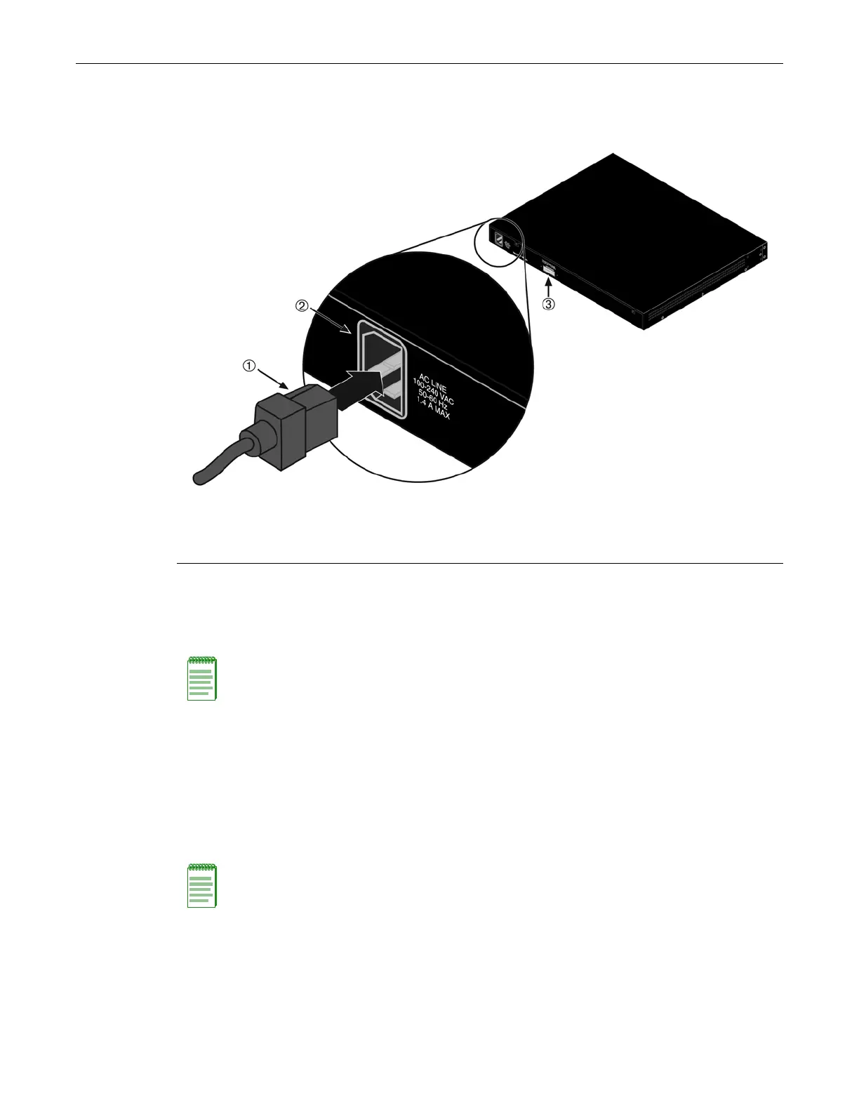
Figure 2-5 Switch Rear View
3. Observe that the power CPU LED (not shown), located on the front panel. During the
initialization, the CPU LED will start by illuminating solid amber, then start blinking green,
then blinking amber, then blinking green again until the end of the initialization, and then
turns solid green.
If the switch is a standalone switch, it will take approximately 30 seconds for the switch to
start up. If the switch is a stack manager, it can take up to 3 minutes or more to initialize all the
switches in the stack, depending on the number of member switches in the stack.
Installing and Connecting a Redundant Power System
You can use the STK-RPS-150PS, a 150W redundant power supply for A4 models.
STK-RPS-150PS
The STK-RPS-150PS can be used as a standalone unit, or you can install an STK-RPS-150PS in the
following RPS shelves:
1 AC power cord 2 AC power connector 3 Redundant power supply connector
Note: If the CPU LED illuminates solid red, there was a critical failure. For more information about
the LED indications and troubleshooting, refer to Chapter 3, Troubleshooting. If you need
additional help, contact Enterasys Networks. Refer to “Getting Help” on page xvii for details
.
Note: The STK-RPS-150PS is a replacement for the C2RPS-PSM. If you already have a
C2RPS-PSM power supply, it can be used in place of the STK-RPS-150PS.
 Loading...