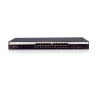
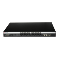
Rack Mounting the Switch
Enterasys A4 Fast Ethernet Switch Hardware Installation Guide 2-3
5. Proceed to “Guidelines for Flat Surface Installation” on page 2-3. For a rackmount installation,
proceed to “Rack Mounting the Switch” on page 2-3.
Guidelines for Flat Surface Installation
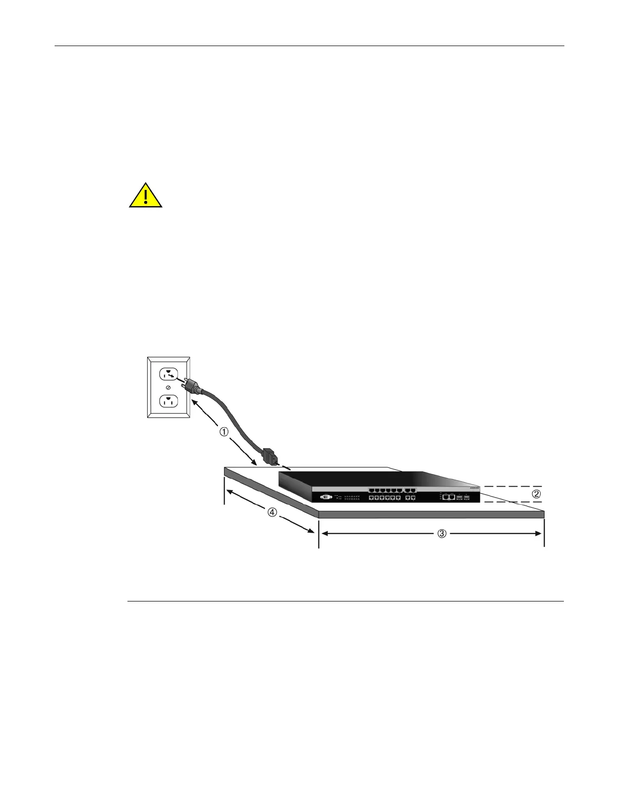
Locate the switch within 182.88 cm (6 ft) of its power source and on a surface as shown in
Figure 2-1 on page 2-3. If an optional redundant power system is going to be installed and
connected to the 14-pin Redundant Power Supply input connector on the rear of the switch,
refer
to “Installing and Connecting a Redundant Power System” on page 2-10.
If you are installing several switches in a stack, proceed to “Connecting Stacking Cables” on
page 2-5. If the switch is being installed as a standalone switch, proceed to “Connecting AC
Power” on page 2-9 for power connection instructions.
Figure 2-1 Area Guidelines for Switch Installation on Flat Surface
Rack Mounting the Switch
To install the switch in a 19-inch rack, you need:
• Two rackmount brackets and mounting screws (rackmount kit) shipped with the switch.
• Four customer-supplied screws to attach the switch to a standard 19-inch rack.
Caution: To ensure proper ventilation and prevent overheating, leave a minimum clearance space
of 5.1 cm (2.0 in.) at the left and right of the switch.
Do not connect the switch to the AC power source until instructed to do so later in the installation
process.
Precaución: Para asegurar una buena ventilación y evitar que el sistema se sobrecaliente, deje un
espacio mínimo de 5.1 cm (2 pulgadas) con respecto a los lados y a la parte posterior del aparato.
No conecte el dipositivo a la fuente primaria hasta que no se le indique.
1 Approximately 152 cm (5 ft) from power source 3 44.5 cm (19.4 in.) for proper ventilation
2 4.45 cm (1.75 in.) per switch. (Vertical clearance
depends on number of switches stacked.)
4 41.9 cm (16.5 in.) for proper ventilation
 Loading...