Connecting to the Console Port for Local Management
2-18 Installation
Connecting to the Console Port for Local Management
This section describes how to install an RS232 DTE interface cable to a PC, a VT series terminal, or
a modem to the A4 for out-of-band sessions using CLI commands.
What Is Needed
The following is a list of interface cables that may be needed to connect the DB9 male Console port
connector on the switch. The cables are terminated by a DB9 female connector at one end, and by
one of three type connectors at the other end, depending on the type connection needed for the
remote device. The cables that may be needed are as follows:
• DB9 female-to-DB9 female (supplied with switch)
• DB9 female-to-DB25 female
• DB9 female-to-DB25 male
Using a DTE modem DB9 female-to-DB9 female cable, you can connect products equipped with a
DB9 DTE male console port to an IBM or compatible PC running a VT series emulation software
package.
Using a DTE modem DB9 female-to-DB25 female cable, you can connect products equipped with
a DB9 DTE male console port to a VT series terminal or VT type terminals running emulation
programs for the VT series.
Using a DTE modem DB9 female-to-DB25 male cable, you can connect products equipped with a
DB9 DTE male console port to a Hayes compatible modem that supports 9600 baud.
The cable used must connect the Console port Received Data, Pin 2 to the Transmitted Data pin at
the other end of the cable. The connection from the Console port Transmitted Data, Pin 3 (must be
connected) to the Received Data pin cable connection at the other end of the cable. The DB9
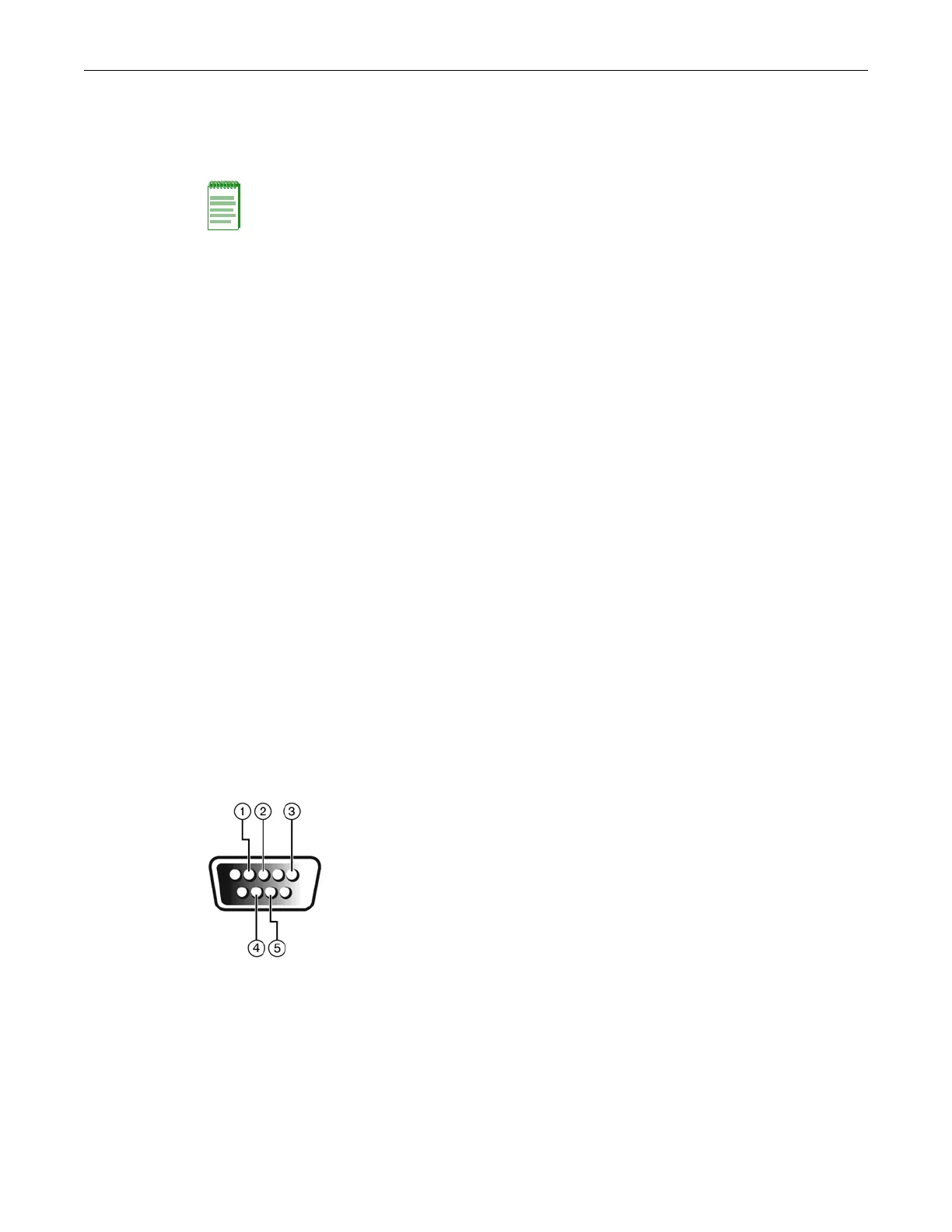
Console port pin assignments are shown in Figure 2-12.
Figure 2-12 DB9 Male Console Port Pinout Assignments
Note: When switches are connected in a stack configuration and all high-speed stacking cables are
connected before powering up the switches, one switch in the stack will be automatically
designated as the Manager of the stack and its Console port will remain active. All other switches
will become Member switches and their Console ports will be deactivated.
1 Pin 2, Received Data (input)
2 Pin 3, Transmitted Data (output)
3 Pin 5, Signal Ground
4 Pin 7, Request to Send
5 Pin 8, Clear to Send
All other pins not connected.
 Loading...