Rack Mounting the Switch
3-8 Hardware Installation
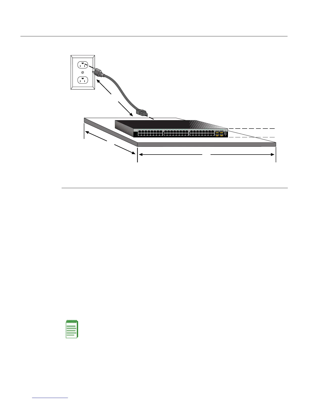
Figure 3-6 Area Guidelines for Switch Installation on Flat Surface
Rack Mounting the Switch
Toinstalltheswitchina19‐inchrack,youneed:
•Tworackmountbracketsandmountingscrewsshippedwiththeswitch.
•Fouruser‐suppliedscrewstoattachtheswitchtoastandard19‐inchrack.
Guidelines for Rackmount Installation
Theinstallationsitemustbewithinreachof thenetworkcablingandmeetthe
requirementslistedbelow:
• Appropriategroundedpowerreceptaclesmustbelocatedwithin152cm(5ft)ofthe
location.
•Atemperatureofbetween5°C(41°F)and40°C(104°F)mustbemaintainedatthe
installationsite
withfluctuationsoflessthan10°C(18°F)perhour.
1 Approximately 152 cm (5 ft) from power source 3 44.5 cm (17.52 in.) for proper ventilation
2 4.45 cm (1.75 in.) per switch. (Vertical clearance
depends on number of switches stacked.)
4 41.9 cm (16.5 in.) for proper ventilation
Console
1
2
45
CPU
UP
RPS
MGR
DOWN
46
47
48
47
48
B2G124-48P
12345678 910111213141516
15
16
17
18
31
32
33
34
17 18 19 20 21 22 23 24 25 26 27 28 29 30 31 32 33 34 35 36 37 38 39 40 41 42 43 44 45 46 47 48 45 46 47 48
Â
À
Ã
Á
Note: To ensure proper ventilation and prevent overheating, leave a minimum clearance
space of 5.1 cm (2.0 in.) at the left, right, and rear of the switch.
 Loading...