Connecting to the Network
SecureStack B2 Installation Guide 3-21
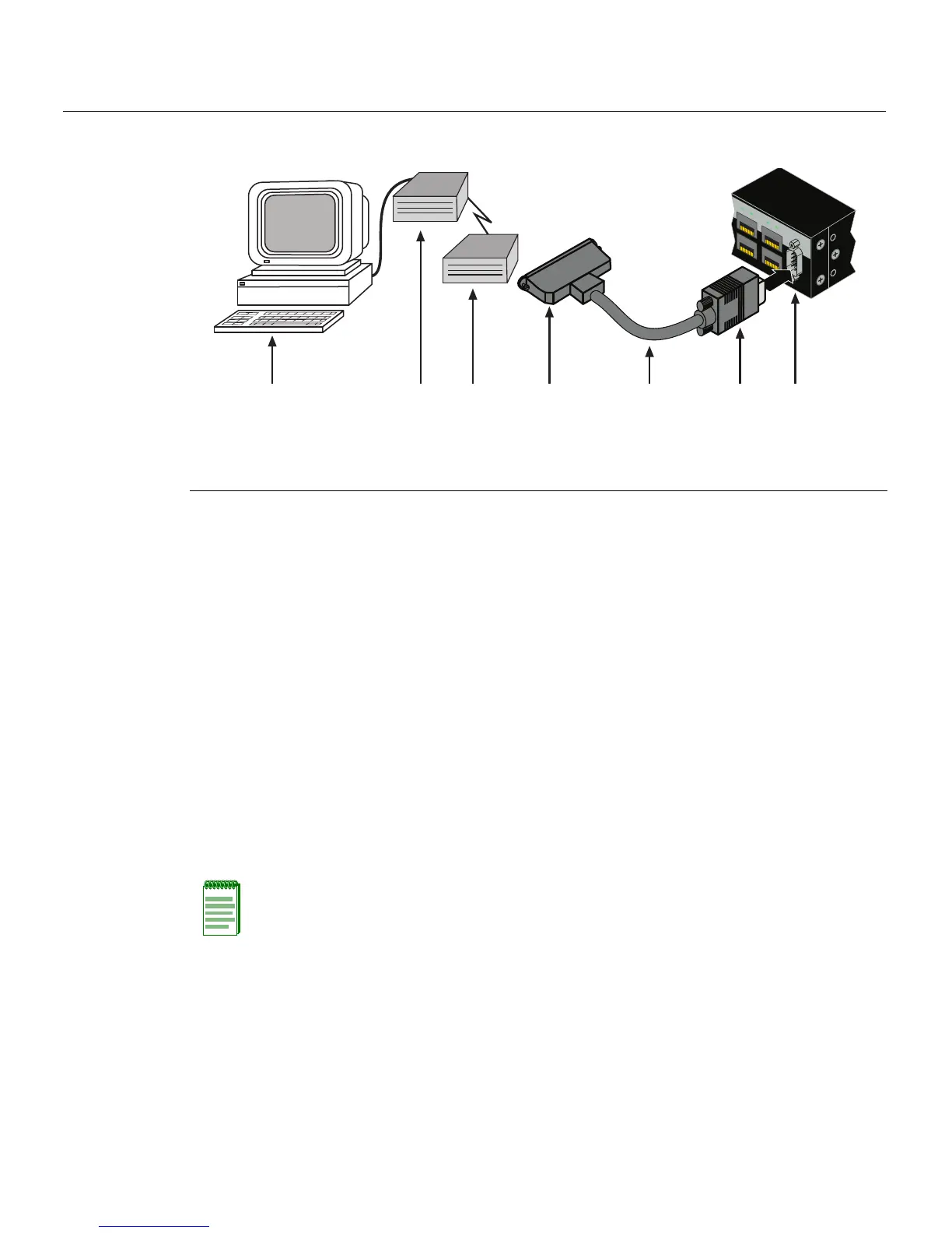
Figure 3-14 Connecting to a Modem
Connecting to the Network
Thefollowingprocedurescoverthecableconnectionsfromthenetworkorotherdevice s
totheswitchRJ45portsoranyinstalledoptionalMini‐GBIC.
• ConnectingUTPCablesonpage 3 ‐21
• ConnectingFiber‐OpticCablestoMT‐RJ Portsonpage 3‐25
• ConnectingFiber‐OpticCablestoLCPortsonpage 3‐
27
Connecting UTP Cables
ThefixedRJ45frontpanelportsare10/100/1000Mbpsportsandhaveinternalcrossovers.
Whenconnectingaworkstationtotheseports,useastraight‐throughcable.When
connectingnetworkingdevicestotheseports,suchasabridge,repeater,orrouter,usea
crossovercable.
Toconnecttwistedpairsegmentstothe
switch,refertoFigure 3‐15andproceedas
follows:
1. Ensurethatthedevicetobeconnectedattheotherendofthesegmentis
powered O N.
2. Connectthetwistedpair segmenttothesw itchbyinsertingtheRJ45connectoronthe
twistedpairsegmentintothedesiredRJ45port(forexample,Port8).
1 DB9 female cable connector 4 DB25 male connector 7 PC with VT emulation application
2 Serial interface cable 5 Local modem
3 DB9 male Console port 6 Remote modem
C2G124-24
C
o
n
so
le
4
5
46
4
7
48
B2G124-48P
4
5
4
6
47
48
ÂÃ Á À
ÄÅÆ
Note: All fixed RJ45 front panel ports support Category 5 Unshielded Twisted Pair (UTP)
cabling with an impedance between 85 and 111 ohms. Category 3 cable may be used if
the connection is going to be used only for 10 Mbps.
 Loading...