Connecting to the Network
3-26 Hardware Installation
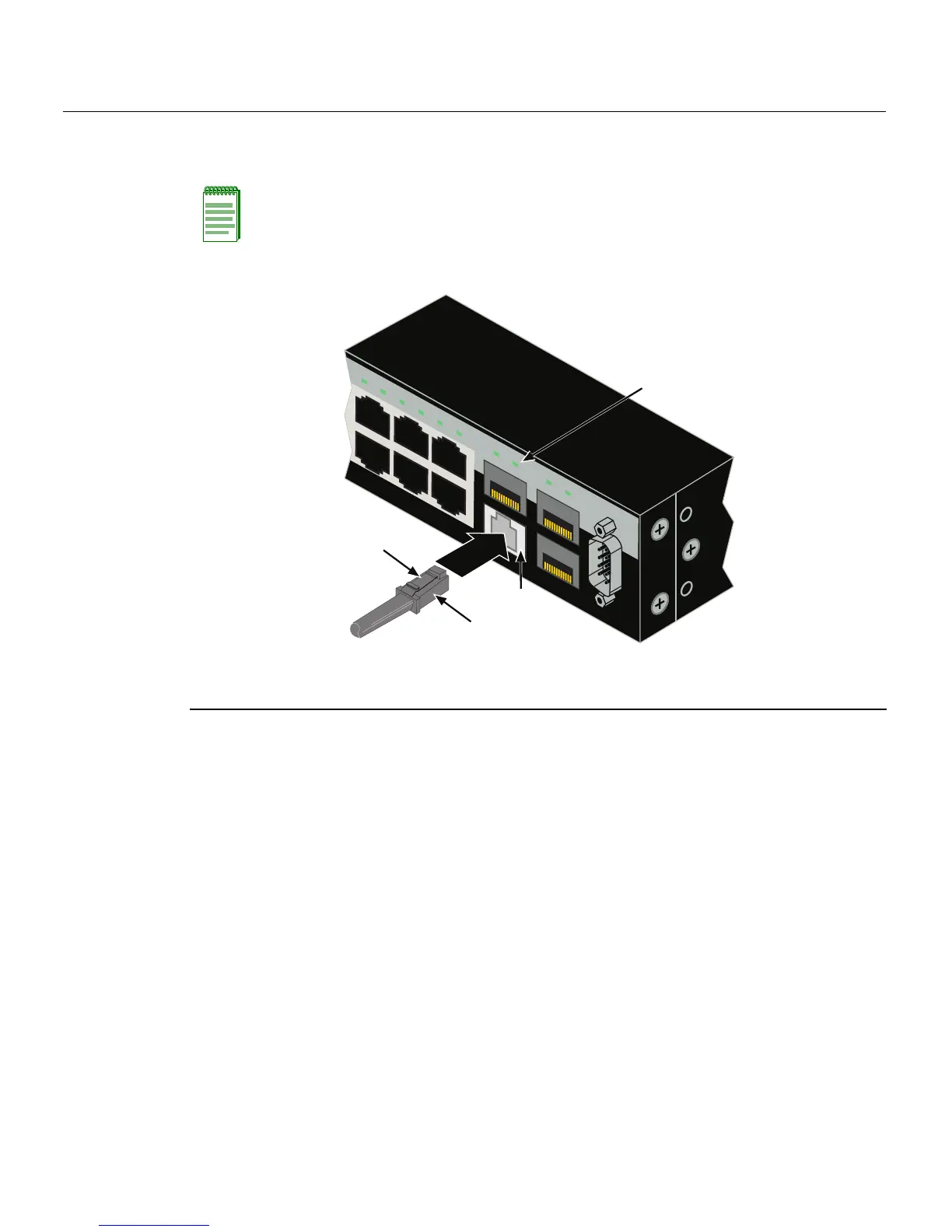
2. InserttheMT‐RJcableconnectorintotheMT‐RJconnectoruntilitclicksintoplace.
Figure 3-20 Cable Connection to MT-RJ Multimode Fiber-Optic Connectors
3. Plug theotherendofthecableintotheappropriateportontheotherdevice.Some
cablesmaybeterminatedattheotherendwithtwoseparateconnectors,oneforeach
fiber‐opticstrand.In
thiscase,ensurethatthetransmi tfiber‐opticstrandisconnected
tothereceiveportandthereceive fiber‐opticstrandtothetransmitport.
4. VerifythatalinkexistsbycheckingthattheportLink/ActivityLEDison(blinking
greenorsolidgreen).IftheLink/ActivityLEDisoff,perform
thefollowingstepsuntil
itison:
a. Verifythatthedeviceatthe otherendofthesegmentisONandconnectedtothe
segment.
b. Ifthereareseparatefiber‐opticconnectionsontheother device,checkthe
crossoverofthecables.Swapthe cableconnectionsifnecessary.
c. Checkthatthefiber
‐opticconnectionmeetsthedBlossandcablespecifications
outlinedintheCablingGuideformultimodecabling.Toobtainthisdocument,
referto“RelatedDocuments”onpage xvi.
Note: To remove the MT-RJ cable connector, press on its release tab and pull out the
cable connector.
1 Mini-GBIC MT-RJ port connector 3 Release tab
2 MT-RJ cable connector 4 Link/Activity LED
C2G124-24
Console
45
46
47
48
47
B2G124-48P
43
44
45
46
47
48
45
46
47
48
À
Â
Á
Ã
 Loading...