Connecting to Console Port for Local Management
3-18 Hardware Installation
Connecting to Console Port for Local Management
ThissectiondescribeshowtoinstallanRS232DTEinterfacecabletoaPC,aVTseries
terminal,oramodemtoanEnterasysC2G124‐24,C2G124 ‐48,orC2H124‐48forout‐of‐
bandsessionsusingCLIcommands.
What Is Needed
Thefollowingisalistofuser‐suppliedDTEinterfacecablesthatmaybe needed toconnect
theDB9male Consoleportconnectorontheswitch.ThecablesareterminatedbyaDB9
femaleconnectoratoneend,andbyoneofthreetypeconnectorsattheotherend,
dependingon
thetypeconnectionneededfortheremotedevice.Thecablesthatmaybe
neededareasfollows:
•DB9female‐to‐DB9female
•DB9female‐to‐DB25female
•DB9female‐to‐DB25male
UsingaDTEmodemDB9female‐to‐DB9femalecable,youcanconnectproducts
equippedwithaDB9DTEmale
consoleporttoanIBMorcompatiblePCrunningaVT
seriesemulationsoftwarepackage.
UsingaDTEmodemDB9female‐to‐DB25femalecable,youcanconnectproducts
equippedwithaDB9DTEmaleconsoleporttoaVTseriesterminalorVTtypeterminals
runningemulationprogramsforthe
VTseries.
UsingaDTEmodemDB9female‐to‐DB25malecab le,youcanconnectproductsequipped
withaDB9DTEmaleconsoleporttoaHayescompatiblemodemthatsupports
9600 baud.
ThecableusedmustconnecttheConsoleportReceivedData,Pin2totheTransmitted
Datapinatthe
otherendofthecable.TheconnectionfromtheConsoleportTransmitted
Data,Pin3(mustbeconnected)totheReceivedDatapincableconnectionatthe otherend
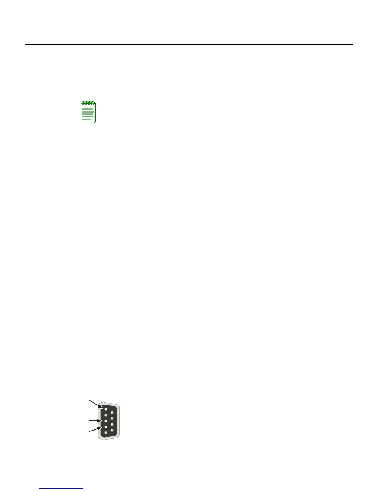
ofthecable.TheDB9ConsoleportpinassignmentsareshowninFigure 3‐9.
Figure 3-9 DB9 Male Console Port Pinout Assignments
Note: When switches are connected in a stack configuration and all high-speed stacking
cables are connected before powering up the switches, one switch in the stack will be
automatically designated as the Manager of the stack and its Console port will remain
active. All other switches will become Member switches and their Console ports will be
deactivated.
1 Pin 2, Received Data (input)
2 Pin 3, Transmitted Data (output)
3 Pin 5, Signal Ground
All other pins not connected.
Â
À
Á
5
1
9
6
 Loading...


