Connecting to the Network
3-22 Hardware Installation
Connecting to the Network
Thefollowingprocedurescoverthecableconnectionsfromthenetworkorotherdevice s
totheswitchRJ45portsoranyinstalledoptionalMini‐GBIC.
• ConnectingUTPCablesonpage 3‐22
• ConnectingFiber‐OpticCablestoMT‐RJPortsonpage 3‐25
• ConnectingFiber‐OpticCablestoLCPortsonpage 3‐
28
Connecting UTP Cables
ThefixedRJ45frontpanelportsare10/100/1000Mbpsportsandhaveinternalcrossovers.
Whenconnectingaworkstationtotheseports,useastraight‐throughcable.When
connectingnetworkingdevicestotheseports,suchasabridge,repeater,orrouter,usea
crossovercable.
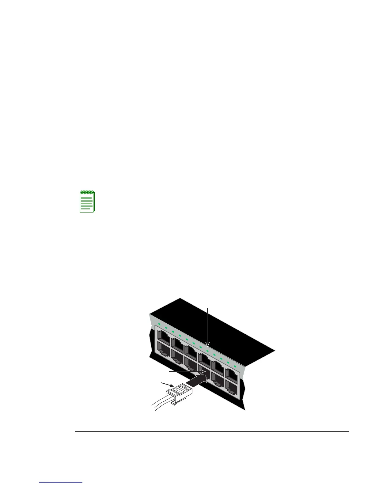
Toconnecttwistedpairsegmentstothe
switch,refertoFigure 3‐13andproceedas
follows:
1. Ensurethatthedevicetobeconnectedattheotherendofthesegmentis
powered ON.
2. ConnectthetwistedpairsegmenttotheswitchbyinsertingtheRJ45connectoronthe
twistedpairsegmentintothedesiredRJ45port(forexample,Port8).
Figure 3-13 Connecting a UTP Cable Segment to RJ45 port
Note: All fixed RJ45 front panel ports support Category 5 Unshielded Twisted Pair (UTP)
cabling with an impedance between 85 and 111 ohms. Category 3 cable may be used if
the connection is going to be used only for 10 Mbps.
1 RJ45 connector 3 Port 8 Link/Activity LED
2 Port 8
1
2
1
2
3
4
5
6
7
8
9
10
11
12
11
12
Â
À
Á
 Loading...


