Connecting to the Network
SecureStack C2 Installation Guide 3-29
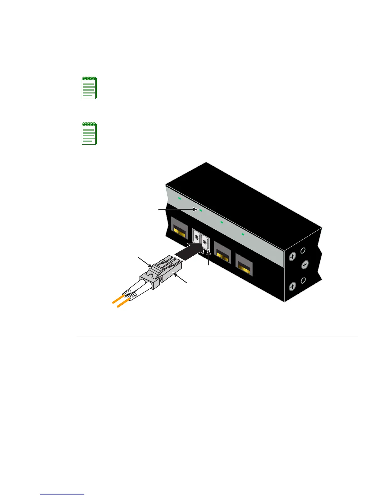
1. Removetheprotectivecovers(notshown)fromthefrontpanelLCfiber‐opticport
(port22inthisexample)andfromtheconnectorsoneachendofthecable.
2. InserttheLCcableconnectorintothe
Mini-GBIC LCconnectoruntilitclicksintoplace.
Figure 3-19 Cable Connection to LC Fiber-Optic Connectors
3. Plugtheotherendofthecableintotheappropriateportontheotherdevice.Some
cablesmaybeterminatedattheotherendwithtwoseparateconnectors,oneforeach
fiber‐opticstrand.Inthiscase,ensurethatthetransmitfiber‐opticstrand
isconnected
tothereceiveportandthereceive fiber‐opticstrandtothetransmitport.
4. VerifythatalinkexistsbycheckingthattheportLink/ActivityLEDison(blinking
greenorsolidgreen).IftheLink/ActivityLEDisoff,performthefollowingstepsuntil
itison:
a. Verifythat
thedeviceattheotherendofthesegmentisONandconnectedtothe
segment.
Note: Leave the protective covers in place when the connectors are not in use to prevent
contamination.
Note: To remove the LC cable connector, press on its release tab and pull it out of
Mini-GBIC
LCconnector.
1 Mini-GBIC MT-RJ port connector 3 Release tab
2 LC cable connector 4 Link/Activity LED
21
22
23
24
21
22
23
24
C2G124-24
À
Â
Á
Ã
 Loading...


