4-2 Troubleshooting
Using LANVIEW
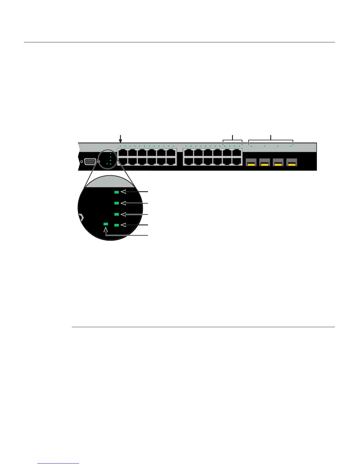
TheseswitchessupporttheEnterasys Networksbuilt‐inLANVIEWLEDvisualdiagnostic
andstatusmonitoringsystem.TheLANVIEWLEDsonboththeC2G124‐24and
C2G124‐48arelocatedinsimilarlocationsasshownonC2G124‐24inFigure 4‐1.The
LANVIEWLEDsontheC2H124‐48areshowninFigure 4‐
2.TheseLEDsallowyouto
quicklyobservenetwork statusfordiagnosingswitchandnetworkproblems.
Figure 4-1 LANVIEW LEDs of C2G124-24 and C2G124-48 (C2G124-24 shown)
1 CPU LED 7 Link/Activity LEDs for 10/100/1000 Mbps for
2 STACK DOWN LED • C2G124-24: RJ45 ports 21 through 24
3 STACK UP LED • C2G124-48: RJ45 ports 45 through 48
4 RPS LED for redundant power-source status 8 Link/Activity LEDs for 1-Gbps Mini-GBIC for
5 Manager LED
• C2G124-24: ports 21 through 24
1
1. These Mini-GBIC ports will only establish a link when the RJ45 port equivalent is not linked on a
C2G124-24 or C2G124-48. (For example; when Mini-GBIC port 45 is linked, RJ45 port 45 is
deactivated. When Mini-GBIC is not linked, the RJ45 port 45 is reactivated and can establish a link
as long as the Mini-GBIC port 45 is not linked first.)
6 Link/Activity LED for
• C2G124-48: ports 45 through 48
1
• C2G124-24/C2G124-48:
10/100/1000 Mbps, RJ45 port 1
• C2H124-48: 10/100/1000 Mbps, RJ45
port 1
Console
1
2
23
24
21 22 23 24
CPU
UP
RPS
MGR
DOWN
123456789101112 131415161718192021222324
11
12
13
14
21 22 23 24
C2G124-24
Æ
Ç
Å
CPU
UP
RPS
MGR
DOWN
Á
Â
Ã
Ä
À
 Loading...


