Safety and operating instructions
© Construction Tools GmbH | 3390 5149 01 | 2020-09-22
Original Instructions
15
3 Overview
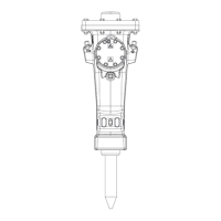
3.1 Equipment description
The picture gives an overview of the main parts and
components of the hydraulic attachment. Actual details
may differ.
Version F
HM Version M
A. Tank line »T«
B. Cooling air openings
C. Leak oil line (not required in all case)
D. Display
E. Magnet plate
F. Control line
G. Pressure line »P«
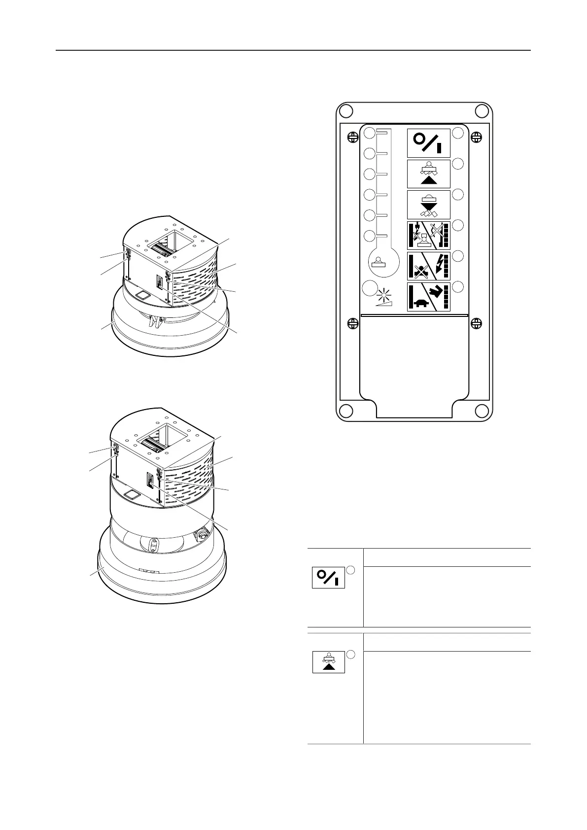
Display
1. Electric power available
2. Magnet plate on „Lift load“
3. Fast demagnetization activated „Drop load“
4. Interruption / Error
5. Overload / System failure
6. Underspeed / Overspeed
7. Relative duty cycle of magnet plate
8. Light sensor
LED 1
Green operation indicator
Power supply voltage available. The
system is switched on and ready for op-
eration.
LED lights up when the generator is
running and supplies voltage.
LED 2
Yellow operation indicator
Magnet plate switched on. „Lifting“.
LED lights up as long as the magnet
plate remains switched on.
Note: If the LED lights after switching on
for about 1-2 seconds and then switches
off again, or if LED 4 lights up, the con-
nection cable of the magnet plate is not
plugged in or interrupted.
 Loading...