S0740 800 179/E071123/P64
-- 1 6 --
ct33_15_1
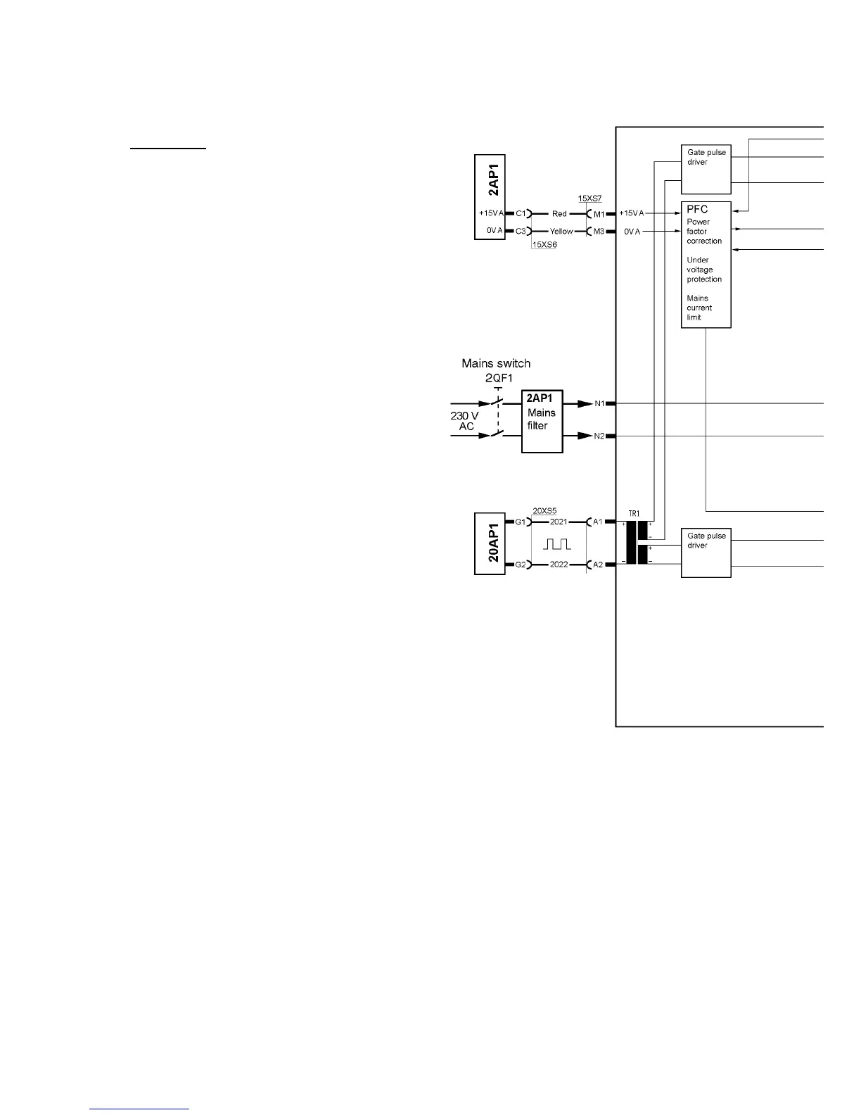
15AP1 Power board
WARNING!
Dangerous voltage - mains voltage.
Never make any measurements on this board
when the machine is connected to the mains
supply.
The power module is a single forward converter,
operating at a switching frequency of 65 kHz.
IGBT transistors are used as the switching
elements. See pages 44 to 47 and 53 to 55 for
measurement instructions.
If the power board has failed, a replacement
board must be mounted in accordance with the
instructions on page 56.
The power board carries the mains rectifier, the
charging circuit, the PFC circuit, the gate circuits
and the switching circuits.
The mains rectifier, the switching transistors and
parts of the charge and PFC circuits are
integrated in a semiconductor module, PM1,
which is part of the power board.
Charging circuit
When the mains power supply is turned on, the rectified mains voltage charges smoothing
capacitor 15C1 via resistor R31. Thyristor TY1 short --circuits charge resistor R31 when the
machine is loaded. If TY1 did not conduct, resistor R31 would burn out when the unit is on
load.
Power facto r corrector (PFC)
The aim with the power factor corrector is to keep the mains current sinusoidal and in phase
with the mains voltage. The PFC circuit holds the intermediate voltage at 365 V. At mains
currents above 26 A the PFC does not work, the intermediate voltage is then 325 V or less.
When the PFC is operatiing properly the voltage across capacitor 15C1 is 365 V.
 Loading...