S0740 800 179/E071123/P64
-- 2 5 --
ct33_18
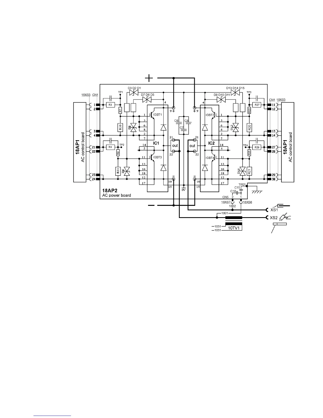
18AP2 AC power board
Sections 18AP2:1 to 18AP2:3 refer to the wiring diagram on page 8.
18AP2:1 Switching circuits
The circuit board carries two IGBT modules IC1 and IC2, with 2 IGBTs each. In
the description below the IGBTs are named IGBT1, IGBT2, IGBT3 and IGBT4.
The IGBTs are controlled by the processor.
All IGBTs are conducting during the starting sequence of the power source
(mains switch power on).
MMA
IGBT1 and IGBT4 are conducting.(positive electrode)
If MMA with negative electrode is selected, IGBT2 and IGBT3 are conducting.
TIG DC
When welding start is activated IGBT1 and IGBT4 conducts.(positive
electrode)
During welding IGBT2 and IGBT3 are conducting (negative electrode).
TIG AC
When welding start is activated IGBT1 and IGBT4 conducts.
During welding IGBT1 and IGBT4 conducts in turns with IGBT2 and IGBT3.
IGBT gate signals
The IGBT gate signals can be measured across varistors D4, D8, D12 and
D16. See page 50 for test instructions.
 Loading...