S0740 800 179/E071123/P64
-- 5 0 --
ct33f3acpwr
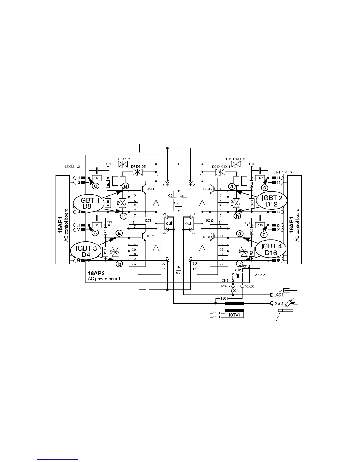
Checking the gate signals to AC power board 18AP2
The gate voltage is +15 V when the IGBTs are conducting.
The gate voltage is -- 10 V when the IGBTs are open.
Measure the gate voltage across varistors D4, D6, D12 and D16.
Measuring points a and b in the diagram.
1. Switch on the machine
2. Select MMA mode and positive polarity. IGBT1 and IGBT4 must be conducting.
3. Select MMA mode and negative polarity. IGBT2 and IGBT3 must be conducting.
If the gate voltage is missing at any of the measurings, check the output from 18AP1 by
measuring across measuring points c and b in the diagram.
Circuit diagram AC power board 18AP2, measuring points gate signals
 Loading...