S0740 800 179/E071123/P64
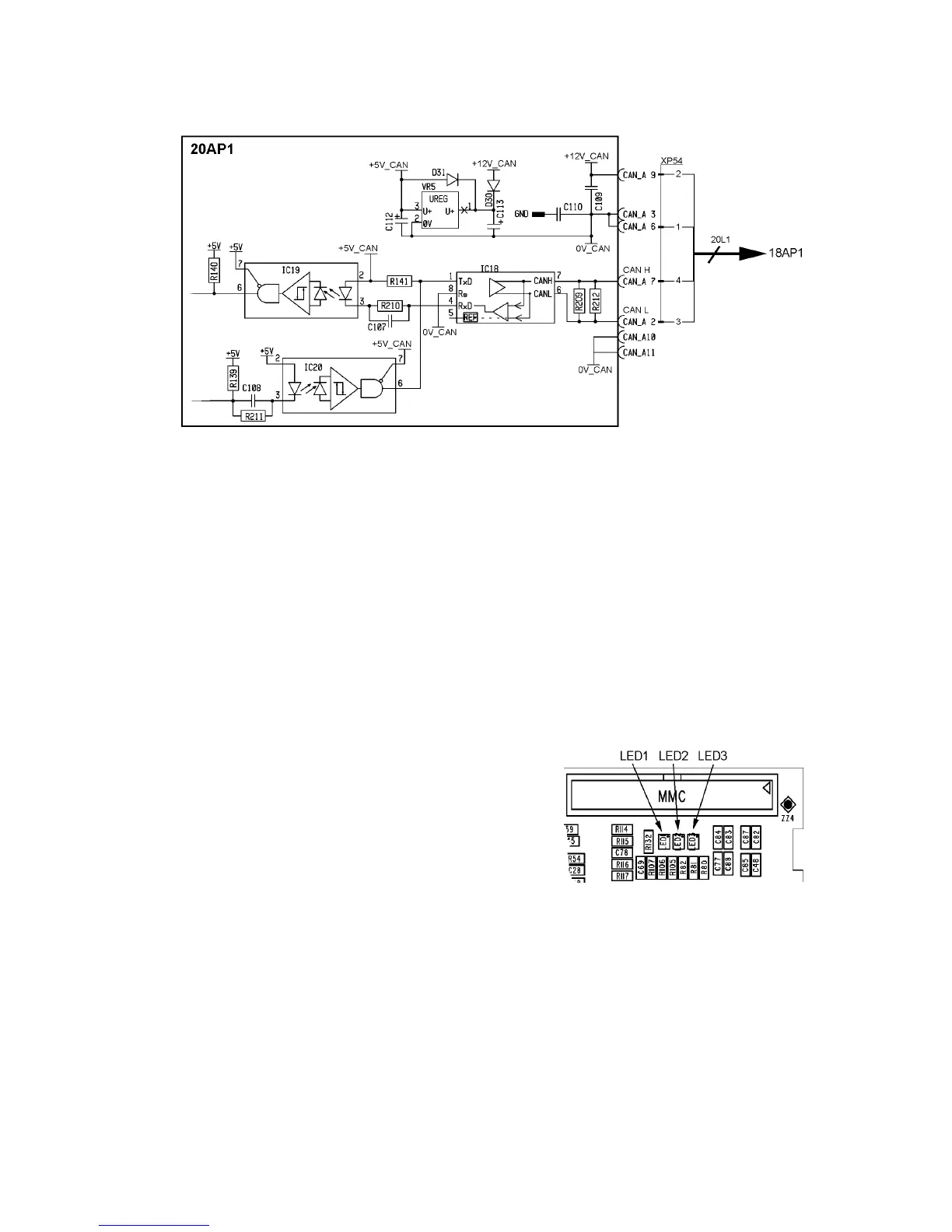
LEDs on circuit board 20AP1
-- 2 9 --
ct33_20
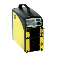
20AP1:2 The CAN bus
Bus communication circuits to and from the control board
A standardised communication (CAN -- Controller Area Network) bus is used
for communication between the units of the machine. Communication speed is
400 kbit/s.
The +12V_CAN and 0V_CAN power supply is unregulated and is galvanically
isolated from other parts of the control board.
The shell of the CAN--connectors and the shield of the CAN cables are
connected to 0V_CAN.
GND in the diagram is connected to the power source chassis.
Voltage regulator VR5 supplies a 5 V power supply to the CAN circuits on
20AP1.
Starting sequence
On power--up, the board’s CAN controller reads in the bus speed from the
micro processor: 400 kbit/s.
The circuit board displays the starting
sequence from power-- up.
LED1 lights red. Then LED1, LED2 and
LED3 lights green.
When the board has been initiated, and the
power source is in the application program,
LED1 flashes continously with a green light.
Communication interruptions
If the CAN bus fails, the control panel will normally generate a fault message.
Check the following points in the event of problems with CAN communications:
S The terminating resistor. The CAN bus resistance must lie in the range
50--130 ohm: the optimum value is 60 ohm. To check the resistance, turn
off the power source and measure the resistance between pins L and K in
connector socket XS25.
 Loading...