S0740 800 179/E071123/P64
-- 5 --
ct33_00
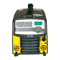
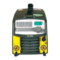
The power source is transistor--controlled, operating on the inverter principle. It consists of a
number of function modules, as shown in the block diagram above. Each module has a
module number, which is always included as the first part of the name/identification of
components in the module.
The modules have the following main functions:
1 MMC module
Control panel and display board.
2 Mains module
Mains interference suppressor, mains switch, auxiliary transformer, contactor.
10 TIG module
Torch switch interface, HF unit, gas valve.
15 Power module
This module is a single forward converter, operating at a switching frequency of 65 kHz.
IGBT transistors are used as the switching elements. All power semiconductors are built
into modules.
18 AC module
Comprises a ll AC TIG functions.
20 Processor board module (controller module)
This is the controller board, 20AP1, that monitors and controls the power source. The micro
processor of the board comprises the welding data unit.
TECHNICAL DATA
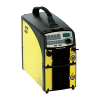
Tig 2200i AC/DC
Mains voltage 230V ±10%, 1∼ 50 Hz
Primary current
I
max
TIG
I
max
MMA
27.4 A
25.0 A
Fuse (anti--surge or type C MCB) 16 A
Open--circuit power 40 W
Setting range TIGAC*/DC
MMA
3 -- 220 A
4 -- 160 A
Permissible load at TIG AC/DC
20% duty cycle
60% duty cycle
100% duty cycle
220 A / 18.8 V
150 A / 16.0 V
140 A / 15.6 V
Permissible load at MMA
30% duty cycle
60% duty cycle
100% duty cycle
160 A / 26.4 V
120 A / 24.8 V
110A/24.4V
Power factor at maximum current
TIG
MMA
0.99
0.99
Efficiency at maximum current
TIG
MMA
66 %
74 %
Open --circuit voltage without VRD function
with VRD function
70 V
30 V
 Loading...
