S0740 800 179/E071123/P64
-- 3 0 --
ct33_20
S All screen connections must be sound. Measure the resistance between
the shell of the CAN connector connected to 20AP1 and the shell of CAN
connector XP55 connected to 18AP1. There must be a short circuit
between those two end points.
S Good contact with the chassis connections from/to the circuit boards and
suppressor capacitors. See the main circuit diagram.
S The connection cable between units. Check that the correct type of cable
is being used. Check that each signal is being carried by the correct core.
CAN H and CAN L must be carried by the twinned pair.
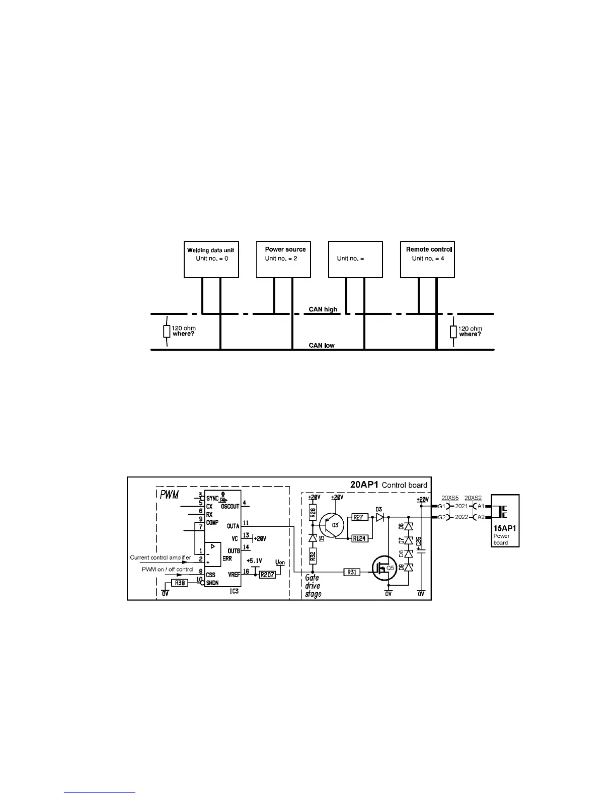
Terminating resistors
In order to avoid communication interference, the ends of the CAN bus must
be terminated by resistive loads.
Principle diagram of the CAN bus and connecting up of the terminating resistors
20AP1:3 Control panel interface circuits
See the service manual for the TA33 AC/DC and TA34 AC/DC control panels,
filename: 0740 800 180.
20AP1:4 Pulse width modulator
The pulse width modulator determines the frequency and pulse time of the
switching transistors’ control pulses. IC3 controls the pulse frequency, the
pulse time and inhibition of pulses.
The pulse frequency is 65 kHz +/-- 1kHz, with a maximum pulse width of 43 --
44 % of the cycle width. See page 53 for screen traces of waveforms and
measurement instructions.
Transistor Q5 controls the primary winding of the pulse transformer on circuit
board 15AP1.
 Loading...