Note
When Fabric Connect is enabled, physical ports 31 and 32 are reserved for internal use.
Refer to Administering VSP Operating System Software for details.
•
RJ45 serial console port used to connect a terminal and perform local management.
•
USB port for access to external storage.
•
RJ45 out-of-band 10/100/1000BASE-T management Ethernet port.
•
LEDs to indicate port status and switch operating conditions. For a description of the LEDs and their
operation, see VSP 7400 Series Switch LEDs on page 61.
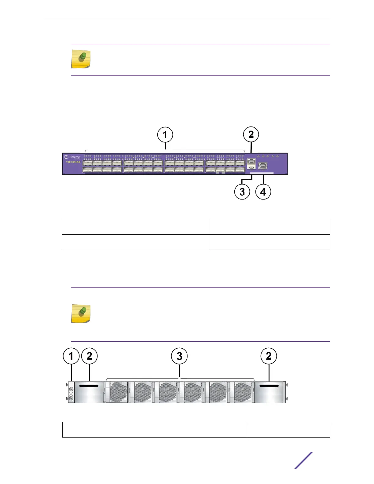
Figure 1: VSP 7432CQ Switch - Front Panel
1 = QSFP28/QSFP+ Ethernet ports 3 = USB port
2 = Console port: RJ45 4 = Management port: RJ45
The rear panel of the VSP 7400 switch includes:
•
Two power supply bays for 750 W AC or DC power supplies.
•
Six bays for replaceable fan modules.
Note
The color of the tab on the fan tray indicates the airflow direction:
•
Red: front-to-back
•
Blue: back-to-front
The operating-system software cannot display the airflow direction.
Figure 2: VSP 7432CQ Switch - Rear Panel
1 = Grounding point 3 = Fan modules
Overview of the VSP 7400 Switches
VSP 7400 Series Switches: Hardware Installation Guide 11

 Loading...

