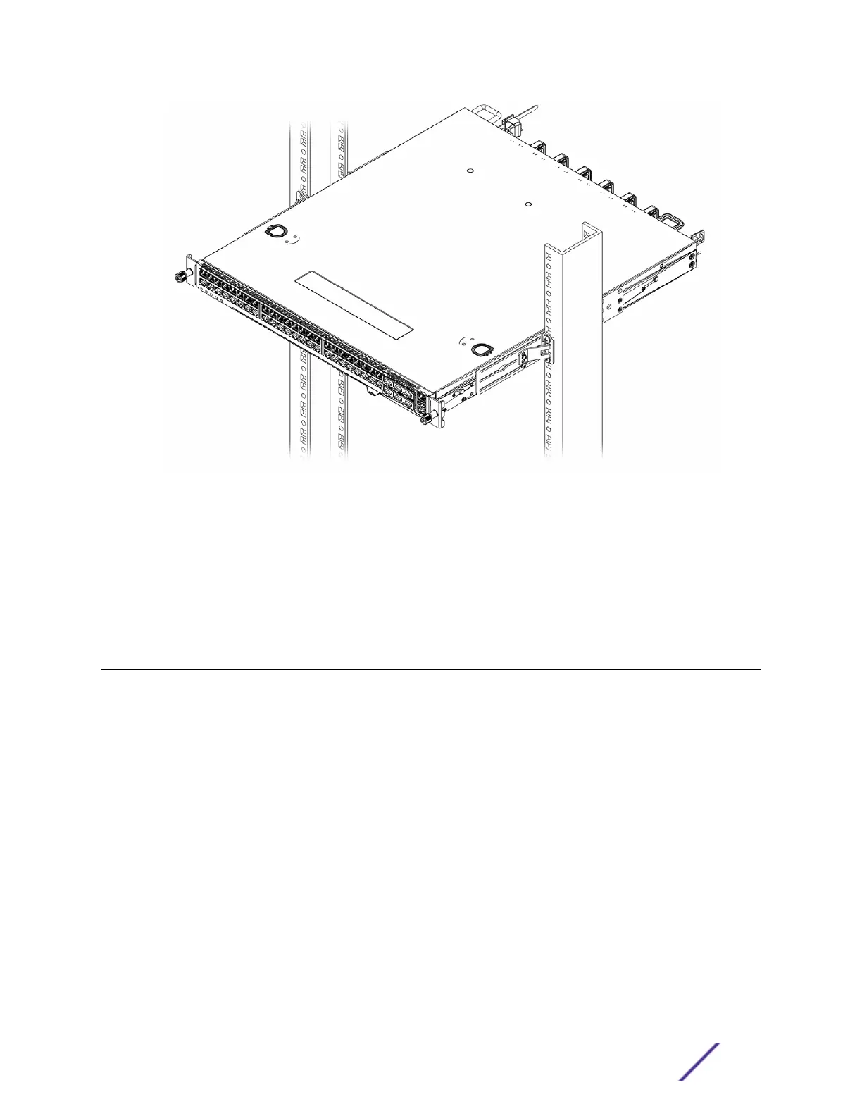
Figure 21: Two-Post Mid-Mount: Complete
7 Verify that the switch is level and is firmly attached to the rack.
If your switch comes with installed AC power supplies, skip to Turn on the Switch on page 52.
If your switch does not have an installed power supply, install one or two power supplies using the
instructions in Installing Internal Power Supplies on page 45.
Installing Optional Components
After the switch is secured to the rack, install optional components.
ExtremeSwitching switches support the use of pluggable transceivers and cables in the SFP+, SFP28,
QSFP+, and QSFP28 formats.
For a list of the optical components supported with ExtremeSwitching devices, see the Extreme Optics
website.
Pluggable Transceiver Modules
Extreme Networks oers several optical transceiver modules for transmitting and receiving data over
optical fiber rather than through electrical wires. Install these modules using the instructions in Extreme
Networks Pluggable Transceivers Installation Guide.
Optical Cables
Direct-attach copper and fiber cables provide connections between unpopulated SFP+, SFP28, QSFP+,
and QSFP28 ports.
Installing Your Switch
VSP 7400 Series Switches: Hardware Installation Guide 44

 Loading...

