750 W AC Power Supply LEDs
The following tables describe the meanings of the LEDs on the 750 W AC power supply (part number
XN-ACPWR-750W-F or XN-ACPWR-750W-R).
The LEDs are located on the end of the power supply unit, arranged vertically to the left of the power
cord receptacle.
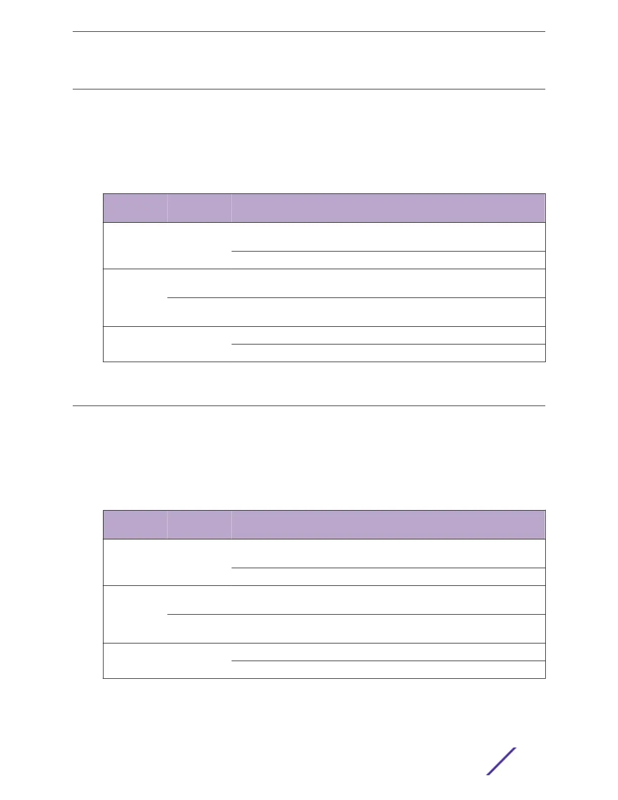
Table 15: 750 W AC Power Supply LED Status Indications
Label and
Color
Description State Meaning
!
Amber
Fault Indicator On
(Solid)
PSU fault
O No PSU fault
DC
(Green)
DC output
Good
On
(solid)
DC output OK
O or
Blinking
DC output fail
AC
(Green)
AC input Good On AC input OK
O AC input fail
750 W DC Power Supply LEDs
The following tables describe the meanings of the LEDs on the 750 W DC power supply (part number
XN-DCPWR-750W-F or XN-DCPWR-750W-R).
The LEDs are located on the end of the power supply unit, arranged vertically to the left of the terminal
block.
Table 16: 750 W DC Power Supply LED Status Indications
Label and
Color
Description State Meaning
!
Amber
Fault Indicator On
(Solid)
PSU fault
O No PSU fault
OUT OK
(Green)
DC output
Good
On
(solid)
DC output OK
O or
Blinking
DC output fail
IN OK
(Green)
DC input Good
"IN OK"
On DC input OK
O DC input fail
Monitoring the Switch
VSP 7400 Series Switches: Hardware Installation Guide 64

 Loading...

