427-0032-00-12, Version 170 Mar 2014 1-5
1 PT-Series Camera Installation
Once the holes are drilled in the mounting surface, install four (4) stainless steel 5/16 or M8 bolts with
stainless steel washers and lock washers through the base of the camera.
Important Note
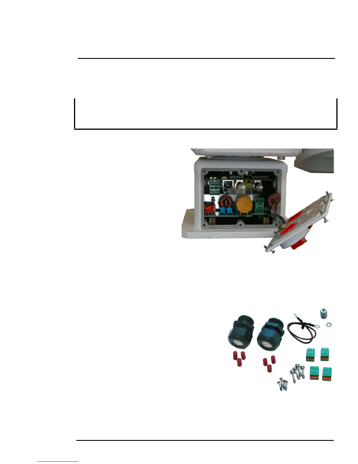
1.5.4 Removing the Back Cover
Use a 2.5mm hex key to loosen the
four captive screws and remove the
cover, exposing the connections at the
back of the camera. There is a
grounding wire connected between the
case and the back cover
1.5.5 Cable Gland Sealing
Proper installation of cable sealing
glands and use of appropriate
elastomer inserts is critical to long term
reliability. Cables enter the camera
mount enclosure through liquid-tight
compression glands. Be sure to insert
the cables through the cable glands on
the enclosure before terminating and
connecting them (the connectors will not fit through the cable gland). Leave the gland nuts loosened
until all cable installation has been completed. Inspect and install gland fittings in the back cover with
suitable leak sealant and tighten to ensure water tight fittings. Teflon tape or pipe sealant (i.e. DuPont
RectorSeal T™) are suitable for this purpose.
1.5.6 Cable Glands and Spare Parts Kit
The kit contains the two 3/4” cable glands and gland
seal plugs required for non-conduit installations.
The remaining parts included in the kit are:
•a spare ground wire
• a spare ground nut and lock washer
• two spare power terminal block plugs
• two spare serial port terminal block plugs
• four spare F-Series back cover screws
• four spare PT-Series back cover screws
Always use stainless steel washers on the four camera base mounting holes, especially in locations
where the camera base is exposed to a damp or salt environment. Ensure that the camera base finish
remains intact when it is secured to its mount. Contact between the stainless steel fasteners and any
bare aluminum will cause galvanic corrosion which will shorten the life of the installation.
 Loading...