01-9
Basic Engine
01-9
OVERHAUL (Continued)
Under no circumstances should the faces of aluminized
intake valves be ground or the valves lapped in as this will
remove the diffused aluminum coating and reduce the
valves’ wear and heat resistant properties. If the valve
faces are worn or pitted it will be necessary to install new
valves and to resurface the valve seats or, alternatively, lap
the seats using dummy valves. The exhaust valves may be
lapped in or the faces ground if required.
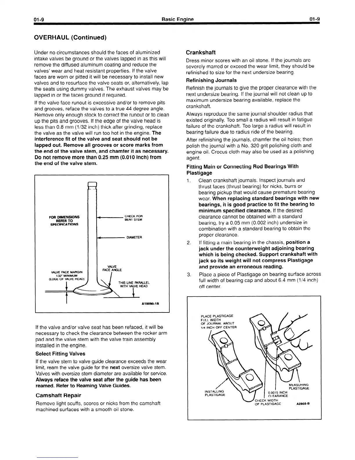
If the valve face runout is excessive and/or to remove pits
and grooves, reface the valves to a true 44 degree angle.
Remove only enough stock to correct the runout or to clean
up the pits and grooves. If the edge of the valve head is
less than 0.8 mm (l/32 inch) thick after grinding, replace
the valve as the valve will run too hot in the engine.
The
interference fit of the valve and seat should not be
lapped out. Remove all grooves or score marks from
the end of the valve stem, and chamfer it as necessary.
Do not remove more than 0.25 mm (0.010 inch) from
the end of the valve stem.
FOR DIMENSIONS
REFER TO
SPECIFICATIONS
If the valve and/or valve seat has been refaced, it will be
necessary to check the clearance between the rocker arm
pad and the valve stem with the valve train assembly
installed in the engine.
Select Fitting Valves
If the valve stem to valve guide clearance exceeds the wear
limit, ream the valve guide for the
next
oversize valve stem.
Valves with oversize stem diameter are available for service.
Always reface the valve seat after the guide has been
reamed. Refer to Reaming Valve Guides.
Camshaft Repair
Remove light scuffs, scores or nicks from the camshaft
machined surfaces with a smooth oil stone.
Crankshaft
Dress minor scores with an oil stone. If the journals are
severely marred or exceed the wear limit, they should be
refinished to size for the next undersize bearing.
Refinishing Journals
Refinish the journals to give the proper clearance with the
next undersize bearing. If the journal will not clean up to
maximum undersize bearing available, replace the
crankshaft.
Always reproduce the same journal shoulder radius that
existed originally. Too small a radius will result in fatigue
failure of the crankshaft. Too large a radius will result in
bearing failure due to radius ride of the bearing.
After refinishing the journals, chamfer the oil holes; then
polish the journal with a No. 320 grit polishing cloth and
engine oil. Crocus cloth may also be used as a polishing
agent.
Fitting Main or Connecting Rod Bearings With
Plastigage
1.
Clean crankshaft journals. Inspect journals and
thrust faces (thrust bearing) for nicks, burrs or
bearing pickup that would cause premature bearing
wear.
When replacing standard bearings with new
bearings, it is good practice to fit the bearing to
minimum specified clearance.
If the desired
clearance cannot be obtained with a standard
bearing, try a 0.05 mm (0.002 inch) undersize in
combination with a standard bearing to obtain the
proper clearance.
2. If fitting a main bearing in the chassis,
position a
jack under the counterweight adjoining bearing
which is being checked. Support crankshaft with
jack so its weight will not compress Plastigage
and provide an erroneous reading.
3. Place a piece of Plastigage on bearing surface across
full width of bearing cap and about 6.4 mm (l/4 inch)
off center.
PLACE PLASTIGAGE
FULL WIDTH
OF JOURNAL ABOUT
114
INCH OFF CENTER
INSTALLING
PLASTIGAGE
-CHECK WIDTH
OF PLASTIGAGE
A28684
 Loading...


