01-27
Basic Enaine
01-27
REMOVAL AND INSTALLATION (Continued)
When installing the ring gear it must be heated evenly to a
temperature of 260 to 280°C (500535°F). Do not exceed
290°C (554°F) as the ring gear wear resistant properties
will be destroyed. If the ring gear is to be heated by direct
flame, place the ring gear on a metal plate approximately 2
to 3 mm (.079--J 18 in.) thick and heat plate from below in
the area of the ring gear until it reaches the required
temperature. The correct temperature can be detected by
using a special type of temperature sensitive crayon. Fit
the ring gear with the chamfers on the leading faces of the
gear teeth relative to the direction of rotation. Allow the ring
gear to cool naturally in air.
Do not quench.
Crankshaft Rear Oil Seal
Removal
1.
Remove the P.T.O. or transmission clutch & pressure
plate.
2. Remove the flywheel.
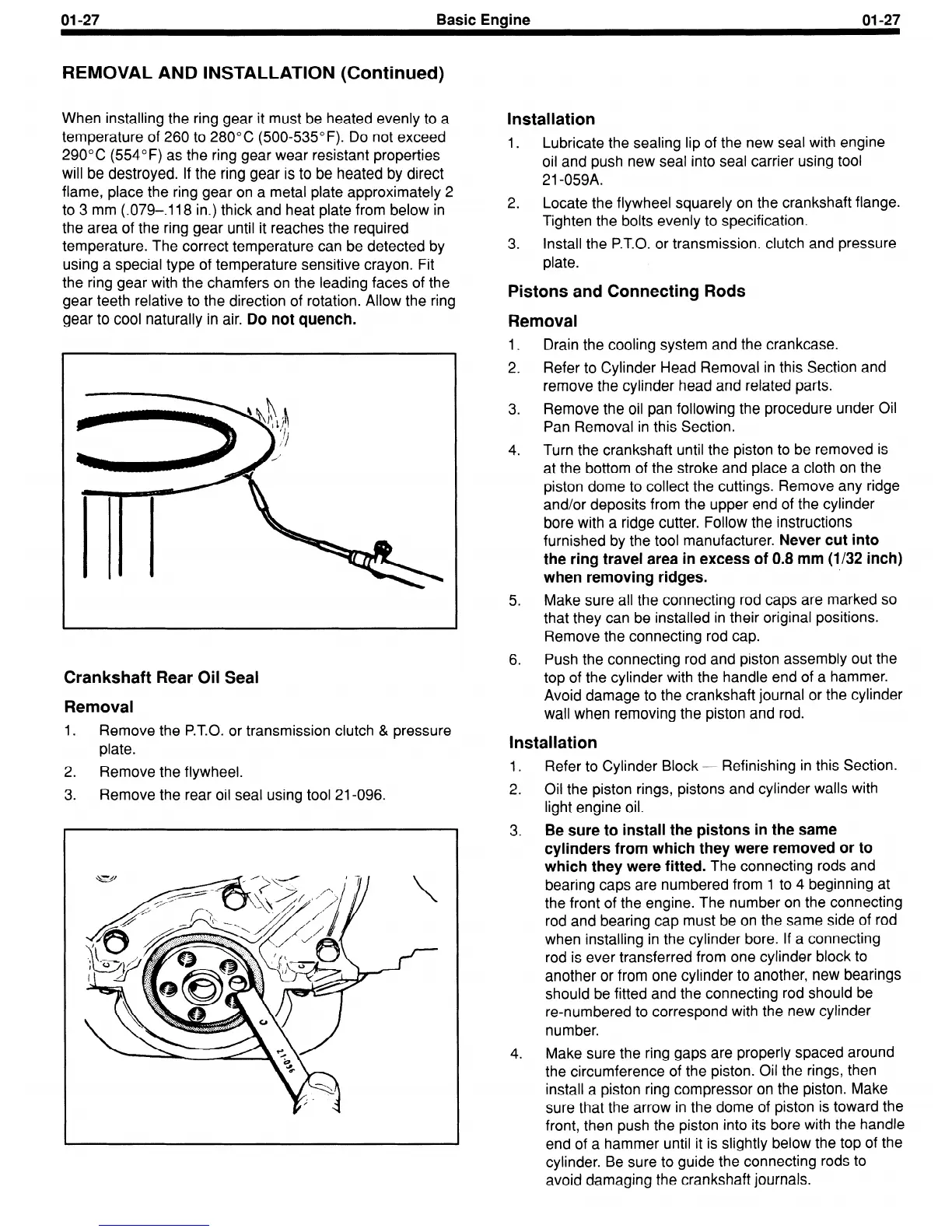
3. Remove the rear oil seal using tool 21-096.
Installation
1. Lubricate the sealing lip of the new seal with engine
oil and push new seal into seal carrier using tool
21-059A.
2.
Locate the flywheel squarely on the crankshaft flange.
Tighten the bolts evenly to specification.
3. Install the P.T.O. or transmission. clutch and pressure
plate.
Pistons and Connecting Rods
Removal
1.
2.
3.
4.
5.
6.
Drain the cooling system and the crankcase.
Refer to Cylinder Head Removal in this Section and
remove the cylinder head and related parts.
Remove the oil pan following the procedure under Oil
Pan Removal in this Section.
Turn the crankshaft until the piston to be removed is
at the bottom of the stroke and place a cloth on the
piston dome to collect the cuttings. Remove any ridge
and/or deposits from the upper end of the cylinder
bore with a ridge cutter. Follow the instructions
furnished by the tool manufacturer.
Never cut into
the ring travel area in excess of 0.8 mm (1132 inch)
when removing ridges.
Make sure all the connecting rod caps are marked so
that they can be installed in their original positions.
Remove the connecting rod cap.
Push the connecting rod and piston assembly out the
top of the cylinder with the handle end of a hammer.
Avoid damage to the crankshaft journal or the cylinder
wall when removing the piston and rod.
Installation
1. Refer to Cylinder Block - Refinishing in this Section.
2. Oil the piston rings, pistons and cylinder walls with
light engine oil.
3.
Be sure to install the pistons in the same
cylinders from which they were removed or to
which they were fitted.
The connecting rods and
bearing caps are numbered from 1 to 4 beginning at
the front of the engine. The number on the connecting
rod and bearing cap must be on the same side of rod
when installing in the cylinder bore. If a connecting
rod is ever transferred from one cylinder block to
another or from one cylinder to another, new bearings
should be fitted and the connecting rod should be
re-numbered to correspond with the new cylinder
number.
4. Make sure the ring gaps are properly spaced around
the circumference of the piston. Oil the rings, then
install a piston ring compressor on the piston. Make
sure that the arrow in the dome of piston is toward the
front, then push the piston into its bore with the handle
end of a hammer until it is slightly below the top of the
cylinder. Be sure to guide the connecting rods to
avoid damaging the crankshaft journals.
 Loading...


