01-10
Basic Enoine
01-10
OVERHAUL (Continued)
4.
Install cap and torque bolts to specifications. Do not
turn crankshaft while Plastigage is in place.
5.
Remove cap. Using Plastigage scale, check width of
Plastigage at widest point to get minimum clearance.
Check at narrowest point to get maximum clearance.
Difference between readings is taper of journals.
6. If clearance exceeds specified limits on the
connecting rod bearings, try a 0.05 mm (0.002 inch)
undersize bearing in combination with the standard
bearings. Bearing clearance must be within specified
limits. If 0.05 mm (0.002 inch) undersize main
bearings are used on more than one journal, be sure
they are all installed in cylinder block side of bearing.
If standard and 0.05 mm (0.002 inch) undersize
bearings do not bring clearance within desired limits,
refinish crankshaft journal, then install undersize
bearings.
7.
After bearing has been fitted, remove Plastigage,
apply light coat of engine oil to journal and bearings.
Install bearing cap. Torque cap bolts to specifications.
8. Repeat procedure for remaining bearings that require
replacement.
Pistons, Pins and Rings
Fitting Pistons
Pistons are available for service in standard sizes and the
oversizes shown in the parts list.
Measure the piston diameter to ensure that the specified
clearance is obtained. It may be necessary periodically to
use another piston that is either slightly larger or smaller to
achieve the specified clearance.
If none can be fitted,
refinish the cylinder to provide the proper clearance for
the piston. When a piston has been fitted, mark it for
assembly in the cylinder to which it was fitted. If the
taper, out-of-round and piston to cylinder bore
clearance conditions of the cylinder bore are within
specified limits, new piston rings will give satisfactory
service. If new rings are to be installed in a used
cylinder that has not been refinished, remove the
cylinder wall glaze (Refer to Cylinder Block,
Refinishing Cylinder Walls). Be sure to clean the
cylinder bore thoroughly.
1.
Calculate the size piston to be used by taking a
cylinder bore check. Follow the procedures outlined
under Cleaning and Inspection.
2.
Select the proper size piston to provide the desired
clearance (refer to the specifications). The piston
should be measured 57.2 mm (2-l/4 inches) below
the dome and at 90” to the piston pin bore.
3. Make sure the piston and cylinder block are at room
temperature 21 degrees
C (70
degrees F).
After any
refinishing operation allow the cylinder bore to
cool, and make sure the piston and bore are clean
and dry before the piston fit is checked.
Fitting Piston Rings
Three piston rings are fitted, two compression and one oil
control ring.
1. Select the proper ring set for the size cylinder bore.
2. Position the ring in the cylinder bore in which it is
going to be used.
3.
Push the ring down into the bore area where normal
ring wear is not encountered.
4. Use the head of a piston to position the ring in the
bore so that the ring is square with the cylinder wall.
Use caution to avoid damage to the ring or
cylinder bore.
5. Measure the gap between the ends of the ring with a
feeler gauge. If the ring gap is less or greater than the
specified limits, try another ring set.
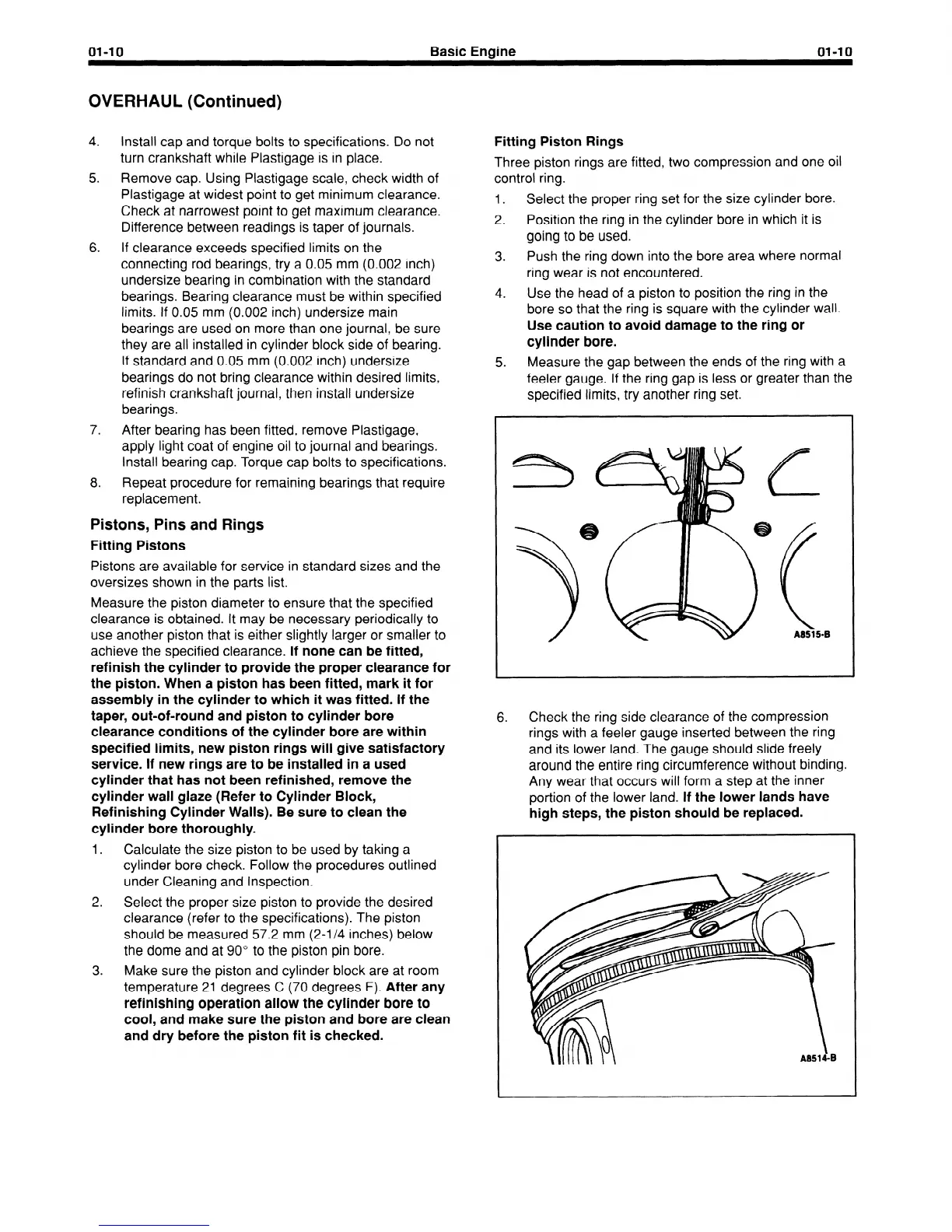
6.
Check the ring side clearance of the compression
rings with a feeler gauge inserted between the ring
and its lower land. The gauge should slide freely
around the entire ring circumference without binding.
Any wear that occurs will form a step at the inner
portion of the lower land.
If the lower lands have
high steps, the piston should be replaced.
 Loading...


