01-15
Basic Enaine
01-15
CLEANING AND INSPECTION (Continued)
A
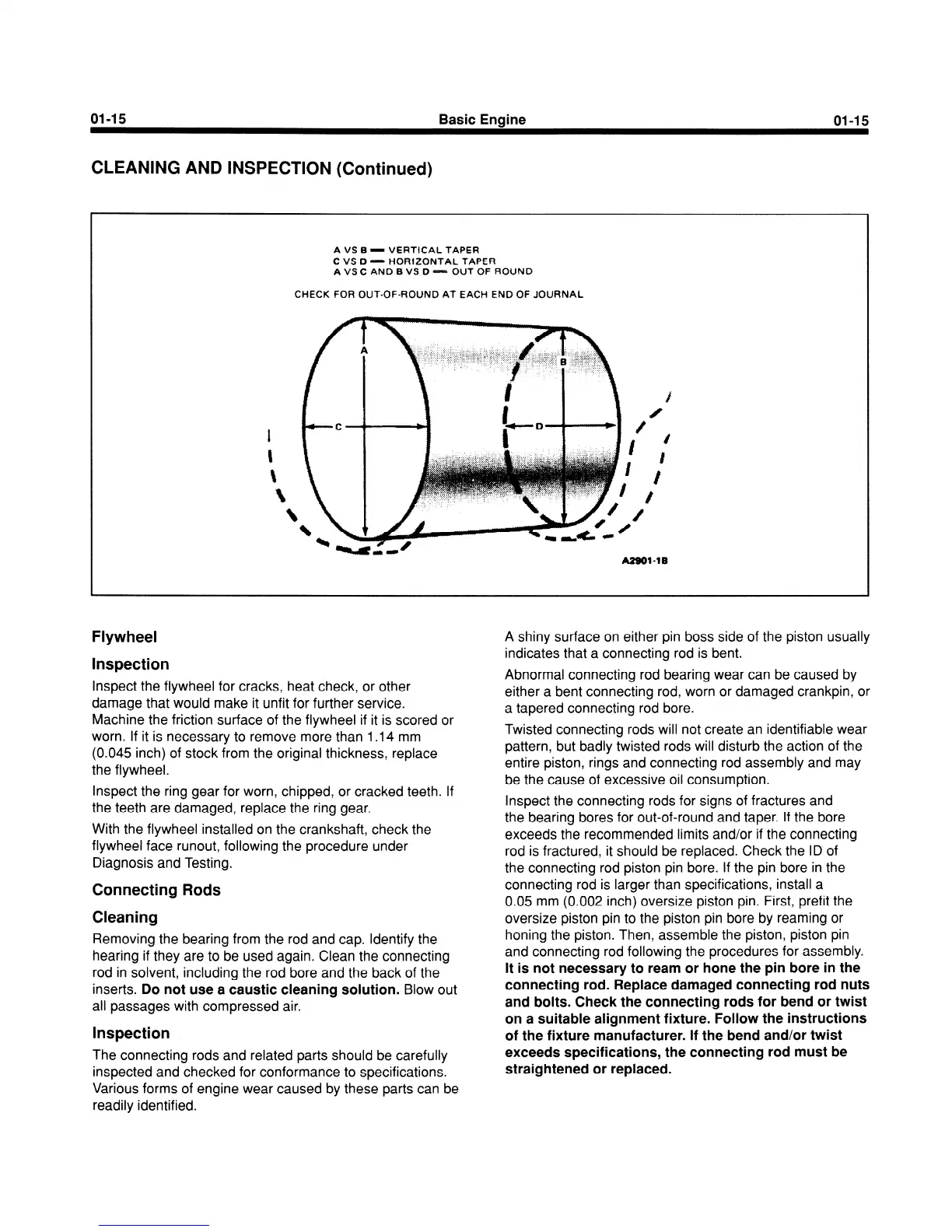
VS 6 - VERTtCAL TAPER
C VS D - HOR12ONTAL TAF’ER
A
VS C AND B VS D - OUT OF ROUND
CHECK FOR OUT-OF-ROUND AT EACH END OF JOURNAL
Flywheel
Inspection
Inspect the flywheel for cracks, heat check, or other
damage that would make it unfit for further service.
Machine the friction surface of the flywheel if it is scored or
worn. If it is necessary to remove more than 1 .I 4 mm
(0.045 inch) of stock from the original thickness, replace
the flywheel.
Inspect the ring gear for worn, chipped, or cracked teeth. If
the teeth are damaged, replace the ring gear.
With the flywheel installed on the crankshaft, check the
flywheel face runout, following the procedure under
Diagnosis and Testing.
Connecting Rods
Cleaning
Removing the bearing from the rod and cap. Identify the
hearing if they are to be used again. Clean the connecting
rod in solvent, including the rod bore and the back of the
inserts.
Do not use a caustic cleaning solution.
Blow out
all passages with compressed air.
Inspection
The connecting rods and related parts should be carefully
inspected and checked for conformance to specifications.
Various forms of engine wear caused by these parts can be
readily identified.
A shiny surface on either pin boss side of the piston usually
indicates that a connecting rod is bent.
Abnormal connecting rod bearing wear can be caused by
either a bent connecting rod, worn or damaged crankpin, or
a tapered connecting rod bore.
Twisted connecting rods will not create an identifiable wear
pattern, but badly twisted rods will disturb the action of the
entire piston, rings and connecting rod assembly and may
be the cause of excessive oil consumption.
Inspect the connecting rods for signs of fractures and
the bearing bores for out-of-round and taper. If the bore
exceeds the recommended limits and/or if the connecting
rod is fractured, it should be replaced. Check the ID of
the connecting rod piston pin bore. If the pin bore in the
connecting rod is larger than specifications, install a
0.05 mm (0.002 inch) oversize piston pin. First, prefit the
oversize piston pin to the piston pin bore by reaming or
honing the piston. Then, assemble the piston, piston pin
and connecting rod following the procedures for assembly.
It is not necessary to ream or hone the pin bore in the
connecting rod. Replace damaged connecting rod nuts
and bolts. Check the connecting rods for bend or twist
on a suitable alignment fixture. Follow the instructions
of the fixture manufacturer. If the bend and/or twist
exceeds specifications, the connecting rod must be
straightened or replaced.
 Loading...


