01-6
Basic Enaine 01-6
DIAGNOSIS AND TESTING
Camshaft Lobe Lift
Compression Test
Check the lift of each lobe in consecutive order and make a
note of the readings.
1. Remove the air cleaner and the valve rocker arm
cover.
2.
Remove the valve rocker arm shaft assembly as
detailed in the pertinent section.
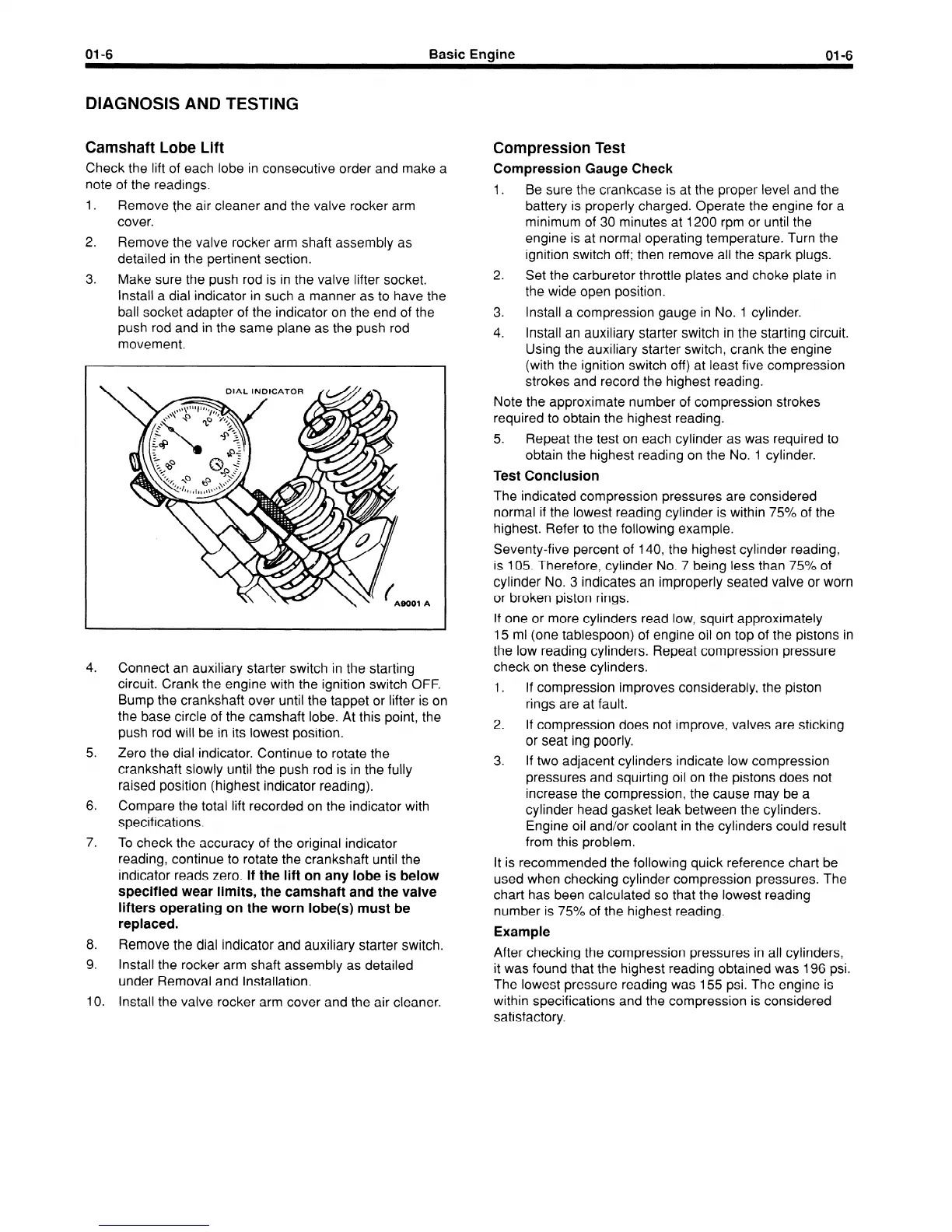
3. Make sure the push rod is in the valve lifter socket.
Install a dial indicator in such a manner as to have the
ball socket adapter of the indicator on the end of the
push rod and in the same plane as the push rod
movement.
Compression Gauge Check
1.
Be sure the crankcase is at the proper level and the
battery is properly charged. Operate the engine for a
minimum of 30 minutes at 1200 rpm or until the
engine is at normal operating temperature. Turn the
ignition switch off; then remove all the spark plugs.
2.
Set the carburetor throttle plates and choke plate in
the wide open position.
3. Install a compression gauge in No. 1 cylinder.
4.
Install an auxiliary starter switch in the starting circuit.
Using the auxiliary starter switch, crank the engine
(with the ignition switch off) at least five compression
strokes and record the highest reading.
Note the approximate number of compression strokes
required to obtain the highest reading.
5.
Repeat the test on each cylinder as was required to
obtain the highest reading on the No. 1 cylinder.
Test Conclusion
1-A
4.
Connect an auxiliary starter switch in the starting
circuit. Crank the engine with the ignition switch OFF.
Bump the crankshaft over until the tappet or lifter is on
the base circle of the camshaft lobe. At this point, the
push rod will be in its lowest position.
5. Zero the dial indicator. Continue to rotate the
crankshaft slowly until the push rod is in the fully
raised position (highest indicator reading).
6. Compare the total lift recorded on the indicator with
specifications.
7.
To check the accuracy of the original indicator
reading, continue to rotate the crankshaft until the
indicator reads zero.
If the lift on any lobe is below
specified wear limits, the camshaft and the valve
lifters operating on the worn lobe(s) must be
replaced.
8. Remove the dial indicator and auxiliary starter switch.
9. Install the rocker arm shaft assembly as detailed
under Removal and Installation.
IO.
Install the valve rocker arm cover and the air cleaner.
The indicated compression pressures are considered
normal if the lowest reading cylinder is within 75% of the
highest. Refer to the following example.
Seventy-five percent of 140, the highest cylinder reading,
is 105. Therefore, cylinder No. 7 being less than 75% of
cylinder No. 3 indicates an improperly seated valve or worn
or broken piston rings.
If one or more cylinders read low, squirt approximately
15 ml (one tablespoon) of engine oil on top of the pistons in
the low reading cylinders. Repeat compression pressure
check on these cylinders.
1.
If compression improves considerably, the piston
rings are at fault.
2.
If compression does not improve, valves are sticking
or seat ing poorly.
3. If two adjacent cylinders indicate low compression
pressures and squirting oil on the pistons does not
increase the compression, the cause may be a
cylinder head gasket leak between the cylinders.
Engine oil and/or coolant in the cylinders could result
from this problem.
It is recommended the following quick reference chart be
used when checking cylinder compression pressures. The
chart has been calculated so that the lowest reading
number is 75% of the highest reading.
Example
After checking the compression pressures in all cylinders,
it was found that the highest reading obtained was 196 psi.
The lowest pressure reading was 155 psi. The engine is
within specifications and the compression is considered
satisfactory.
 Loading...


