03-l 2
Fuel Svstem
03-I 2
ZENITH MODEL #33 CARBURETOR (Continued)
2.
3.
4.
5.
6.
7.
8.
9.
10.
11.
12.
13.
14.
15.
e. Welch plug (31) over spark vacuum port
f. Spark vacuum tube (32) to approximately 14 mm
(9/l 6 inch) from casting
g. Throttle body plug (36) flush
h. Pump check valve (42) flush using tool Cl 51-53.
i.
Well tube (44) making sure that end openings
align with notch in casting at top and fuel channel
at bottom.
Slide seal (33) over throttle shaft with lip toward lever
and install shaft in body.
Back out throttle stop screw (35) and pace body on
bench with mounting flange up.
With milled flat up, install throttle plate (30) with short
side toward idle port and start screws (28). Make sure
beveled sides of plate are next to throttle body bore.
Tap the plate lightly (plate held closed) to center it and
tighten screws.
While holding throttle closed, screw idle stop screw
(35) in until it touches the casting, then screw in an
additional 3/4 turn.
Install idle needle (27) washer (56) and spring (26)
and screw in to gently touch the seat. Back screw out
approximately one turn.
Install power jet valve (14) using Cl 61-9 wrench. No
gasket required.
Install main jet (22) and seat firmly with screwdriver.
No gasket required.
Install main jet plug (20) and washer (21) and tighten
securely. If main jet adjustment or solenoid shutoff are
used, install in place of plug.
Turn body right side up. Insert float axle (13) into
holes in float (12).
Lower float axle and float into slot provided in body
with the float needle sticking into the threaded
opening.
Install the fuel valve seat (19) and washer (18)
making sure that the fuel valve enters the seat
properly (the valve will enter the seat more easily if
the float is held in the up position) and tighten
securely.
Insert float axle clip (11) in slot to bear against axle
ends. Holding axle in place, raise float by applying
light finger pressure to the float bracket. Float
pontoons should be approximately level when the
valve is seated. If not, bend tab to carefully adjust.
Install O-ring (54) on venturi skirt and place venturi
(IO) into recess provided in body making sure that the
nozzle (9) lines up with the notch in the fuel well.
Place intake gasket (8) in position on body.
NOTE: If you have an older model unit with
removable accelerator jet; after intake gasket (8) is in
place, an additional washer (55) will be assembled
over the accelerator jet tube (47) and set inside the
large hole in the intake gasket (8) and on top of the
smaller washer (48). Lower air intake carefully onto
bowl and fasten securely and evenly using attaching
screws (5).
16. Place accelerator pump diaphragm (37) in place on
body with bagged section into cavity. Insert
diaphragm protector (38) into end of spring (39) and
install spring with protector against diaphragm.
17. Place cover (40) over spring and compress. Insert
screws (41) and tighten evenly and securely.
NOTE: Pump spacer (57) will install into cover before
assembly if required.
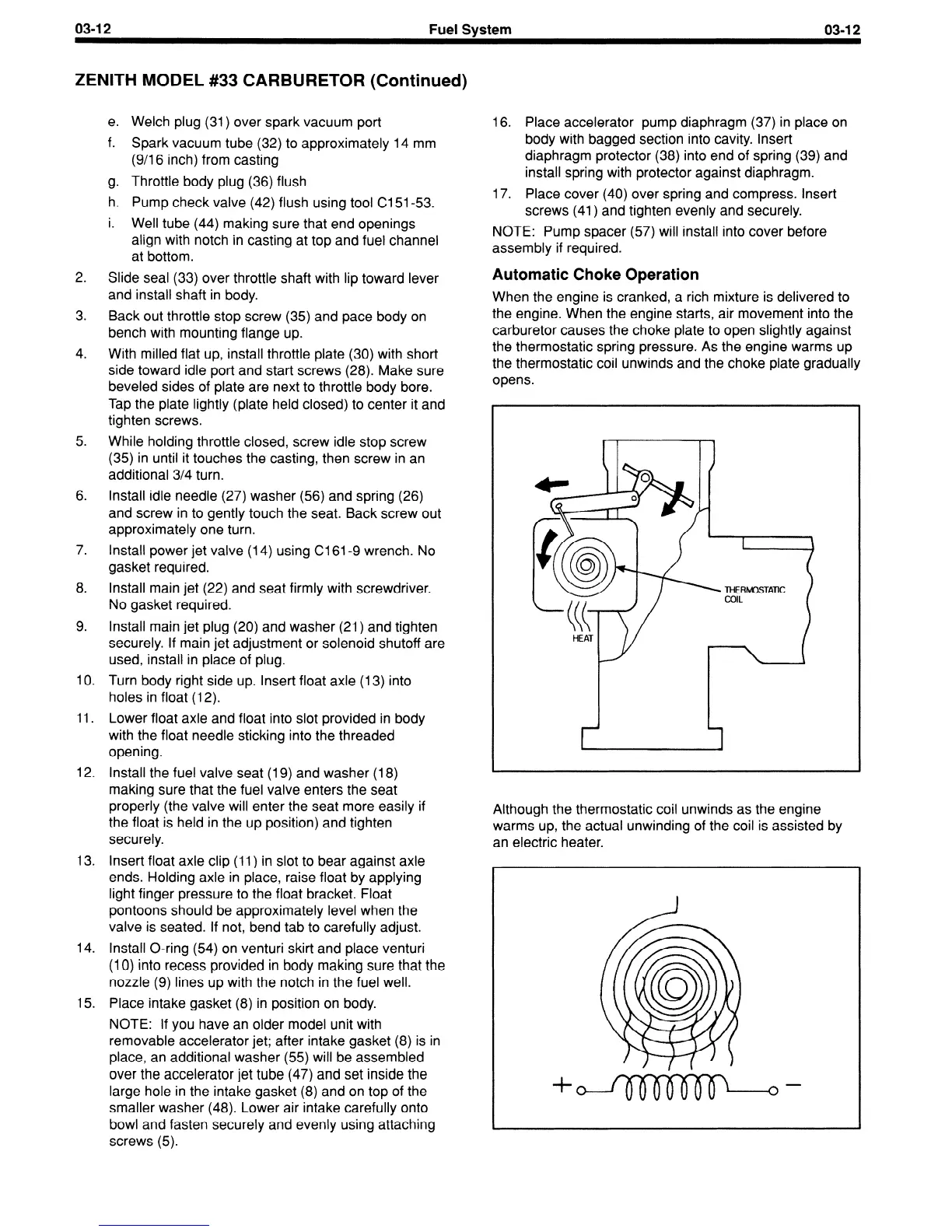
Automatic Choke Operation
When the engine is cranked, a rich mixture is delivered to
the engine. When the engine starts, air movement into the
carburetor causes the choke plate to open slightly against
the thermostatic spring pressure. As the engine warms up
the thermostatic coil unwinds and the choke plate gradually
opens.
 Loading...


