01-22
Basic Engine
01-22
REMOVAL AND INSTALLATION (Continued)
Installation
1.
2.
3.
4.
5.
6.
7.
8.
9.
Cover the valve grooves with plastic tape, slide the
new seal onto the valve stem, remove the tape.
NOTE: The exhaust valves are fitted with umbrella
type seals. The intake valves have the “positive”
guide mounted seals which must be pressed on with
a special service tool.
Position the valve spring and retainer over the valve
stem.
Compress the valve spring using the special service
tool. Position the valve spring retainer locks in the
valve stem grooves and slowly release the spring to
engage the locks in the retainer. Remove the air hose
and adapter.
Lubricate both ends of the push rods with Lubriplate
or equivalent and install them in their respective
bores. Install the rocker arm shaft assembly to the
cylinder head, locating the push rods on the adjusting
screws. Tighten the bolts evenly to specifications.
Adjust valve clearances to specification.
Install the rocker cover with a new gasket and torque
the attaching screws to specification.
Install the spark plugs.
Locate the spark plug leads in the rocker cover clip
and reconnect them to their respective plugs.
Install the air cleaner assembly.
Water Pump
Removal
1.
Drain the cooling system.
2.
Loosen the governor adjusting bolts and remove drive
belt.
3.
Loosen the alternator adjusting and mounting bolts.
Pivot the alternator towards the engine and remove
the drive belt.
4.
Remove the fan and pulley attaching bolts. Remove
the fan and pulley.
5.
Loosen the clamps and remove the lower hose from
the water pump.
6.
Remove bolts securing water pump to cylinder block
and remove the pump and gasket.
Installation
1.
Make sure that the mating faces of cylinder block and
pump are clean.
2.
Position the pump and gasket on the cylinder block
and secure with the attaching bolts.
3.
Position lower hose on water pump and tighten the
clamp.
4.
Position the pulley and fan and secure with bolts.
Torque the bolts to specification.
5.
Position drive belt over crankshaft, fan and alternator
pulley and adjust the belt tension to specifications
using Tool No. T63L-8620-A. Tighten the alternator
mounting and adjusting bolt to specifications.
6.
Position the governor drive belt to governor and fan
pulley. Adjust the belt to specification. Tighten
adjusting bolts.
7.
Refill radiator and install cap. Start the engine and
check for leaks.
Cylinder Front Cover and Timing Chain, or
Crankshaft Sprockets
Removal
1.
Drain the engine coolant by opening the drain cock on
the radiator and removing the drain plug in the
cylinder block.
2.
3.
4.
5.
6.
7.
8.
9.
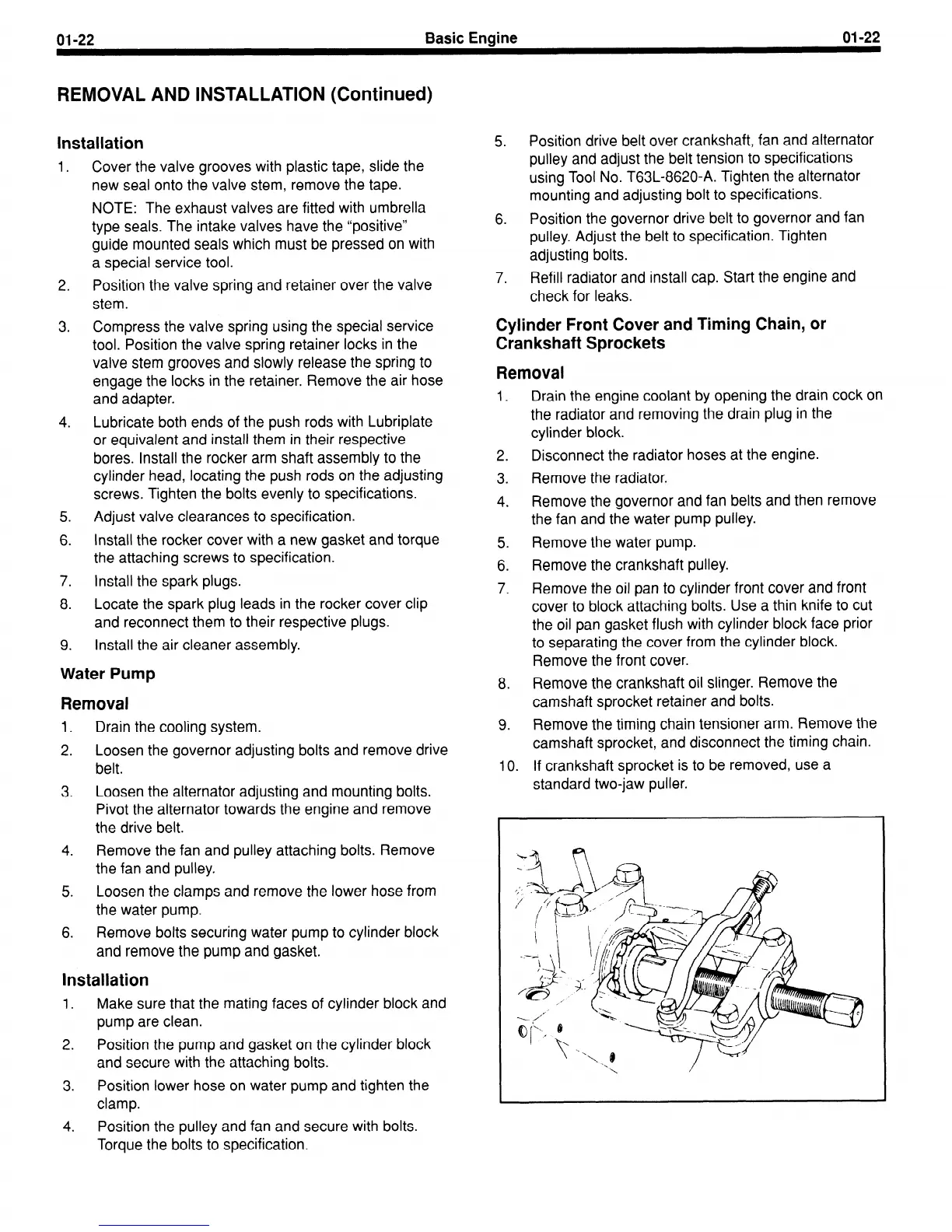
10.
Disconnect the radiator hoses at the engine.
Remove the radiator.
Remove the governor and fan belts and then remove
the fan and the water pump pulley.
Remove the water pump.
Remove the crankshaft pulley.
Remove the oil pan to cylinder front cover and front
cover to block attaching bolts. Use a thin knife to cut
the oil pan gasket flush with cylinder block face prior
to separating the cover from the cylinder block.
Remove the front cover.
Remove the crankshaft oil slinger. Remove the
camshaft sprocket retainer and bolts.
Remove the timing chain tensioner arm. Remove the
camshaft sprocket, and disconnect the timing chain.
If crankshaft sprocket is to be removed, use a
standard two-jaw puller.
 Loading...


