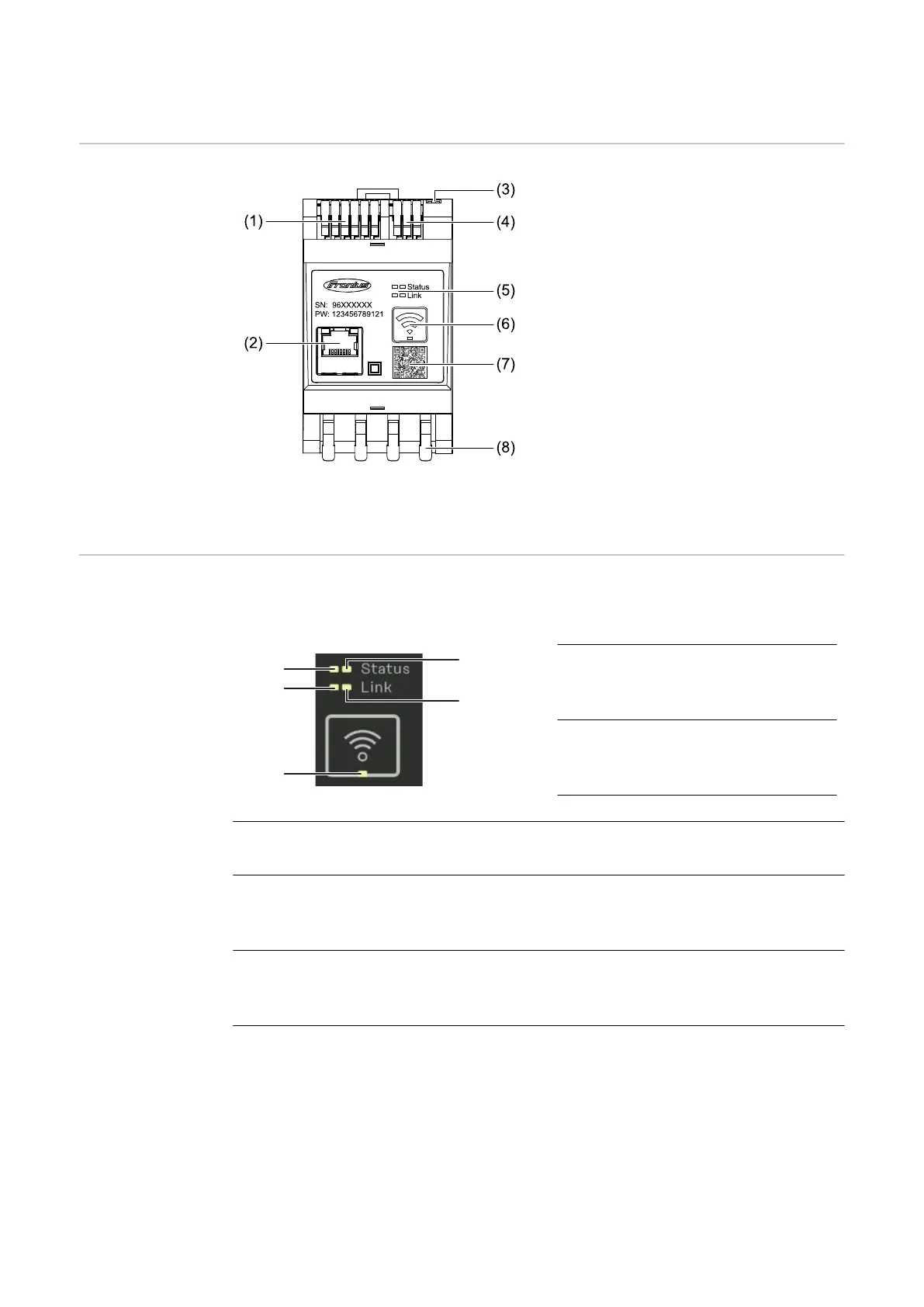
Control elements, connections and displays
Product over-
view
(1) Voltage transformer connection
area
(2) LAN port
(3) DIP switch
-
BIAS
-
Terminating resistor
(4) Modbus RTU connection area
(5) LED indicators
(6) WLAN access point and reset
function button
-
Activate WLAN access
point
-
Carry out device reset
(7) QR code to start the Setup wiz-
ard
(8) AC connection area
LED status indic-
ators
The LED status indicators show the operating status and data connection of the
Fronius Smart Meter IP.
(1) Status 1 LED
Lights up green: Ready for
operation
(2) Status 2 LED
Lights up: Device starting up /
restarting
(3) Link 1 LED
Steady green: Data connection established with the network
(4) Link 2 LED
Lights up red: No data connection
Flashing red: Open WLAN access point
(5) WLAN LED
Flashing green: WLAN connection is being established
Lights up green: WLAN connection is active
14

 Loading...