To avoid interference, the terminating resistor must be used (see chapter Setting
the Modbus RTU terminating resistor on page 25).
If a battery is installed in the system, the BIAS switch must be set (see chapter
Setting the Modbus RTU BIAS on page 26).
Further settings are necessary on the user interface of the inverter and the
Fronius Smart Meter IP (see Advanced settings).
IMPORTANT!
A loose wire can disable an entire area of the network. The data communication
connections of the Fronius Smart Meter IP are electrically isolated from hazard-
ous voltages.
Further information for commissioning
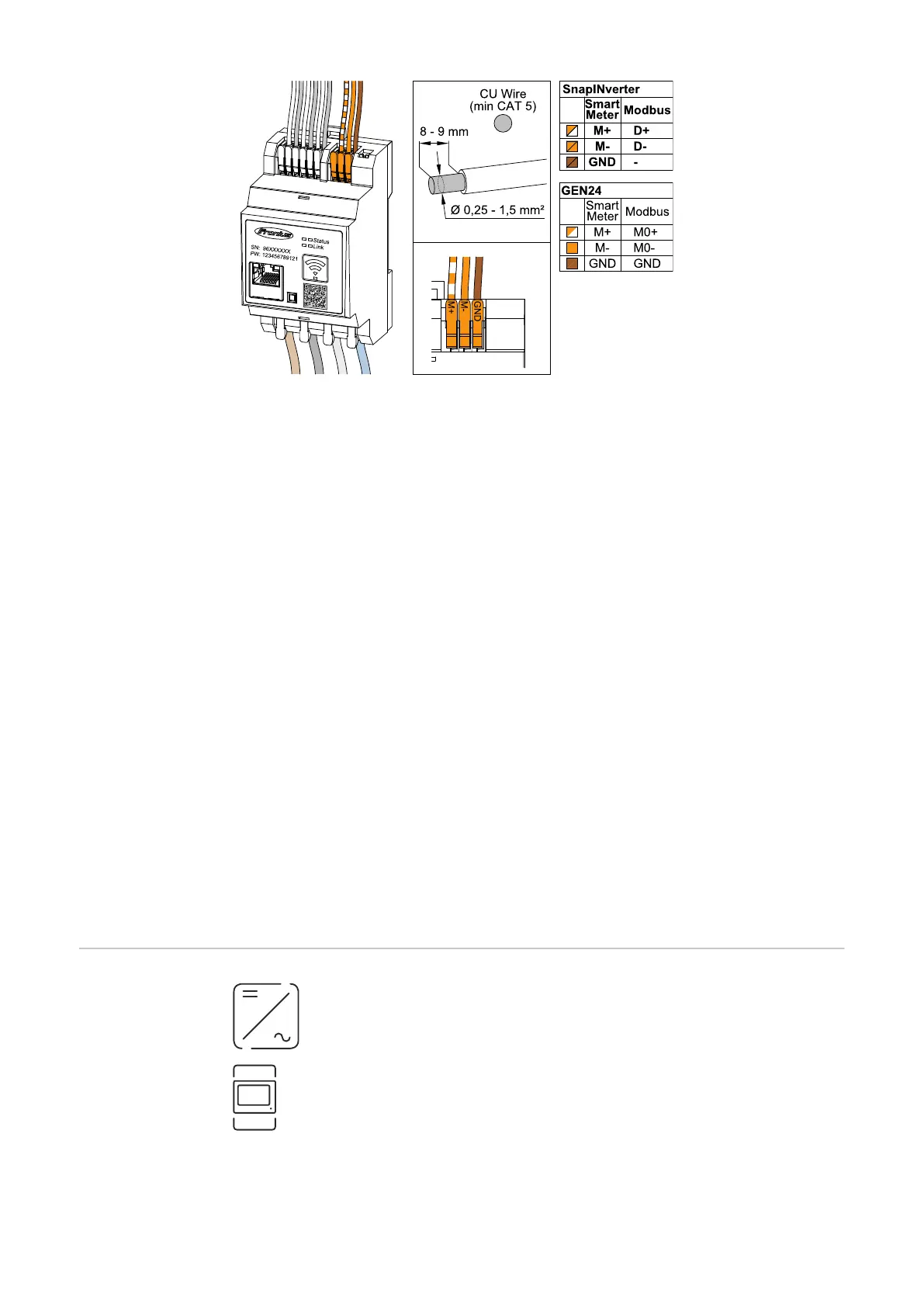
Observe the following information on connecting the data communication cable
to the inverter.
-
Use a shielded CAT 5 STP (Shielded Twisted Pair) or higher data cable to
avoid interference.
-
Use a mutual twisted cable pair for corresponding data lines (D+/D-, M1+/
M1-).
-
If the data lines are laid close to the mains cabling, cables or wires that are
designed for 300 to 600 V must be used (never less than the operating
voltage).
-
Use double-insulated or sheathed data lines when they are close to bare con-
ductors.
-
Two wires can be installed in each terminal; the wires are twisted first, inser-
ted into the terminal and tightened.
Terminating res-
istors - Explana-
tion of symbols
Inverter in the system
e.g. Fronius Symo
Meter - Fronius Smart Meter IP
Terminating resistor is set to ON with the DIP switch.
24

 Loading...