6
Click the Settings button.
7
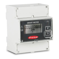
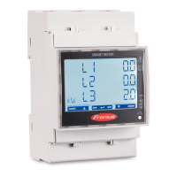
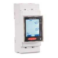
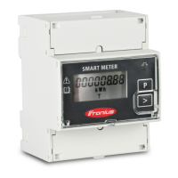
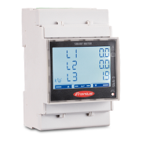
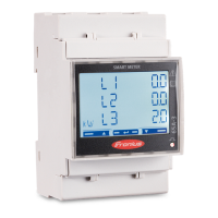
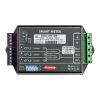
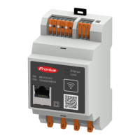
If using Fronius Smart Meter (TCP), enter the IP address of the Fronius
Smart Meter IP. A static IP address is recommended for the Fronius Smart
Meter.
8
Set the position of the meter (feed-in point or consumption point). For more
information on the position of the Fronius Smart Meter IP, see Positioning on
page 12.
9
Click the Ok button when the OK status is displayed. If the Timeout status is
displayed, try again.
10
Click the button to save the settings.
The Fronius Smart Meter IP is configured as the primary meter.
The Current general view menu area displays the power of the PV modules, self-
consumption, the energy fed into the grid and the battery charge (if available).
Configuring sec-
ondary meters
1
Log in to the Smart Meter IP (IP WLAN: 192.168.250.181) and change the
Modbus address accordingly under Advanced settings > Data interface >
Modbus address accordingly (1 = primary meter)
IMPORTANT
A Modbus address can only be assigned once.
2
Open the Fronius Datamanager 2.0 user interface.
-
Open a browser.
-
In the address bar of the browser, enter the IP address (for WLAN:
192.168.250.181, for LAN: 169.254.0.180) or the host and domain name
of the Fronius Datamanager 2.0 and confirm.
-
The Fronius Datamanager 2.0 user interface is displayed.
3
Click the Settings button.
4
Log in to the login area with the service user and the service password.
5
Call up the Meter menu area.
6
Select the secondary meter from the drop-down list.
7
Click the Add button.
8
Enter the name of the secondary meter in the Name input field.
9
Enter the previously assigned address in the Modbus address input field. The
secondary meter address must match the Modbus address set on the Smart
Meter IP.
10
Add meter description.
11
Click the button to save the settings.
The Fronius Smart Meter IP is configured as a secondary meter.
Modbus parti-
cipants - Fronius
SnapINverter
Modbus RTU: A maximum of 4 Modbus participants can be connected to the
Modbus terminal.
Modbus TCP: A maximum of 7 secondary meters can be used in the system.
IMPORTANT!
Only one primary meter, one battery and one Ohmpilot can be connected per in-
verter. Due to the high data transfer of the battery, the battery occupies 2 parti-
cipants.
34
 Loading...
