Connecting the
current trans-
formers
1
Make sure that the current trans-
formers match the live phases.
Make sure that current trans-
former L1 measures the current on
the same phase that is monitored
by voltage input L1. The same ap-
plies for phases L2 and L3. This is
the only way to display correct
measured values.
2
Make sure that the current trans-
formers are pointing in the correct
direction.
NOTE!
Observe direction information when
installing the current transformers
Negative power values occur when the
current transformers are connected in-
correctly.
▶
Observe the data sheet and the
marking on the current trans-
former (arrow indicates the direc-
tion to the load or to the public
grid)
▶
Check the correct position of the
black and white cable.
3
Note down the nominal current of the current transformer for each meter.
These values will be required for commissioning.
4
Attach the current transformers to the conductor to be measured and con-
nect the current transformer cables to the Fronius Smart Meter IP.
WARNING!
Danger from mains voltage
An electric shock can be fatal.
▶
Switch off the power supply before disconnecting live conductors.
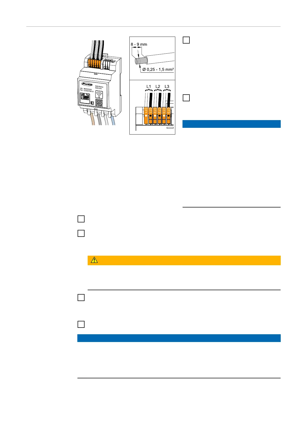
5
Connect the current transformers to the terminals CT1 (white / black), CT2
and CT3. Excessively long cables can be shortened accordingly. Observe the
sequence in which the phases are connected.
6
Route the mains conductors through the current transformers (see Cabling).
NOTE!
Cable length of the current transformers
Cables that are too long can have a negative effect on the measuring accuracy.
▶
If a cable extension is necessary, use a shielded 0.34 to 1.5 mm2 (AWG
22-16) CAT 5 STP (Shielded Twisted Pair) cable rated for 300 V or 600 V
(higher than the operating voltage).
22

 Loading...