Ethernet:
1
open access point
192.168.250.180
2
1
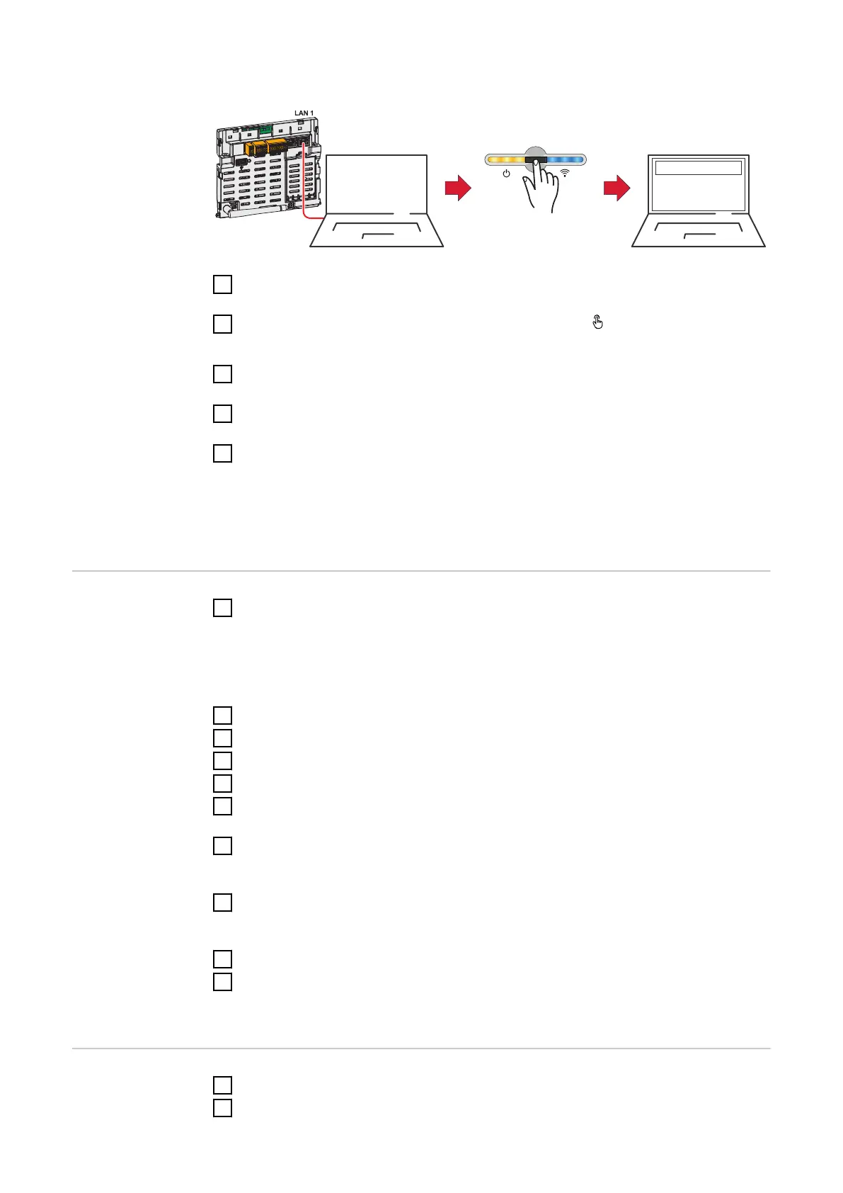
Establish a connection to the inverter (LAN1) with a network cable (CAT5
STP or higher).
2
Open the access point by touching the sensor once
ü
Communication LED flashes blue.
3
In the browser address bar, enter IP address 169.254.0.180 and confirm. The
installation wizard is opened.
4
Follow the installation wizard in the individual sections and complete the in-
stallation.
5
Add the system components in Fronius Solar.web and start up the PV sys-
tem.
The network wizard and the product setup can be carried out independently of
each other. A network connection is required for the Fronius Solar.web installa-
tion wizard.
Configuring the
primary meter
1
Call up the user interface of the inverter.
-
Open a browser.
-
In the address bar of the browser, enter the IP address (for WLAN:
192.168.250.181, for LAN: 169.254.0.180) or the host and domain name
of the inverter and confirm.
-
The user interface of the inverter is displayed.
2
Click the Device configuration button.
3
Log in to the login area with the Technician user and the technician password.
4
Access the Components menu area.
5
Click the Add component button.
6
Select connection type (Fronius Smart Meter (RTU) or Fronius Smart Meter
(TCP)).
7
In the Position drop-down list, set the position of the meter (feed-in point or
consumption point). For more information on the position of the Fronius
Smart Meter IP, see Positioning on page 12.
8
If using Fronius Smart Meter (TCP), enter the IP address of the Fronius
Smart Meter IP. A static IP address is recommended for the Fronius Smart
Meter.
9
Click the Add button.
10
Click the Save button to save the settings.
The Fronius Smart Meter IP is configured as the primary meter.
Configuring sec-
ondary meters
1
Establish a connection to the Smart Meter IP (IP WLAN: 192.168.250.181).
2
Open a browser.
39

 Loading...