- 0.2–2 Hz
- 2–20 Hz
- 20–200 Hz
- 200–2000 Hz
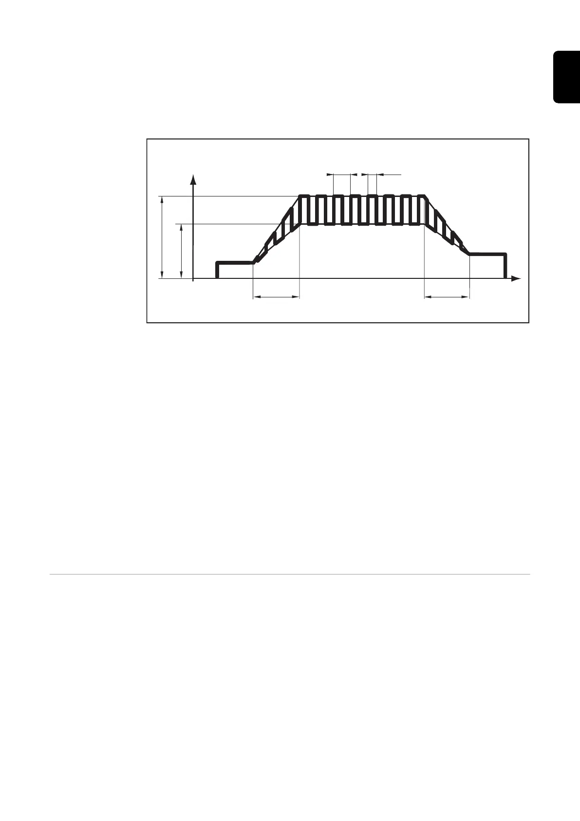
The illustration below shows TIG pulsing with the DC welding process selected.
)3
GF<
,
,
W
W
XS
W
GRZQ
,
6
,
(
,
TIG pulsing - welding current progression curve
- IS ........... Starting current
- IE ........... Final current
- tUp ........ UpSlope
- tDown ... DownSlope
- F-P ........ Pulse frequency
(1/F-P = time between two pulses)
- dcY........ Duty cycle
- I2 .......... Base current
- I1 .......... Main current
(6) Power source connection socket ... for connecting the remote control to the
power source
(7) Foot remote control connection socket ... for connecting the foot remote con-
trol TR 52mc. Particularly advantageous for manual TIG welding. The pulse
welding current can be changed during the welding process (e.g. variable mater-
ial thickness).
TIG foot remote
control TR 52mc
The TIG foot remote control TR 52mc is especially suitable for welding complicated
workpiece shapes.
51
EN-US
 Loading...