Page 13 of 28 Fuji Electric Europe GmbH
5.4.5 Communication ports
FRENIC-Lift (LM2) has up to three communication ports built-in. CAN bus is accessible by removable terminal
TERM1 in I/O terminals board. RS-485 port 1 is accessible by RJ-45. RS-485 port 2 is accessible by I/O
terminals board terminals DX+ and DX-.
Port 1 (Keypad, Modbus RTU, Loader software, DCP)
Port 2 (Modbus RTU, Loader software, DCP)
For additional information about communication protocols refer to specific manual.
6. Hardware configuration
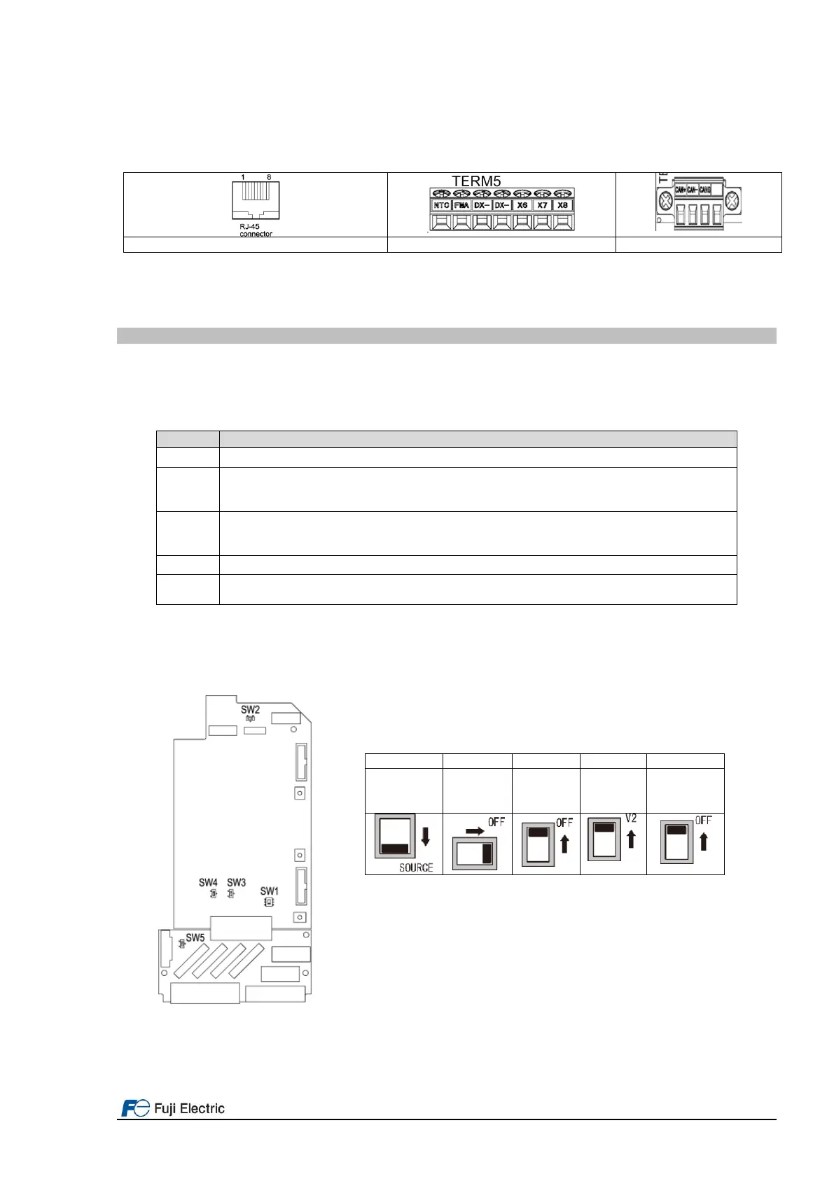
Up to 5 slide switches can be found in the control and I/O terminals boards. With these switches different
configurations can be set. Function of each switch and it possible configurations are shown in table 6.1.
Table 6.1: Configuration of the slide switches
Slide switches factory setting
Digital inputs operation mode selection between PNP and NPN (SINK/SOUCE).
Terminating resistor of RS-485 communications port 1. Port 1 is in RJ-45 connector.
(When keypad or converter for FRENIC Loader is used, set SW2 to OFF position).
(When DCP or Modbus communication is used, set SW2 to ON position if needed).
Terminating resistor of RS-485 communications port 2. Port 2 is in I/O terminals board.
(When converter for FRENIC Loader is used, set SW3 to OFF position).
(When DCP or Modbus communication is used, set SW3 to ON position if needed).
[V2] terminal function selection between V2 (0 to ±10 VDC) and C1 (4 to 20 mADC).
Terminating resistor of CAN communications port.
(When CANopen communication is used, set SW5 to ON position if needed).
By using the PTC input, the cut-off (stopping) function of the inverter does not fulfil EN81-20/50.
Figure 6.1 shows the position of the slide switches in the control and I/O terminals board. It shows as well the default
position (factory default) of each switch.
Figure 6.1 Slide switches position and meaning

 Loading...


