Page 26 of 28 Fuji Electric Europe GmbH
13. Alarm messages
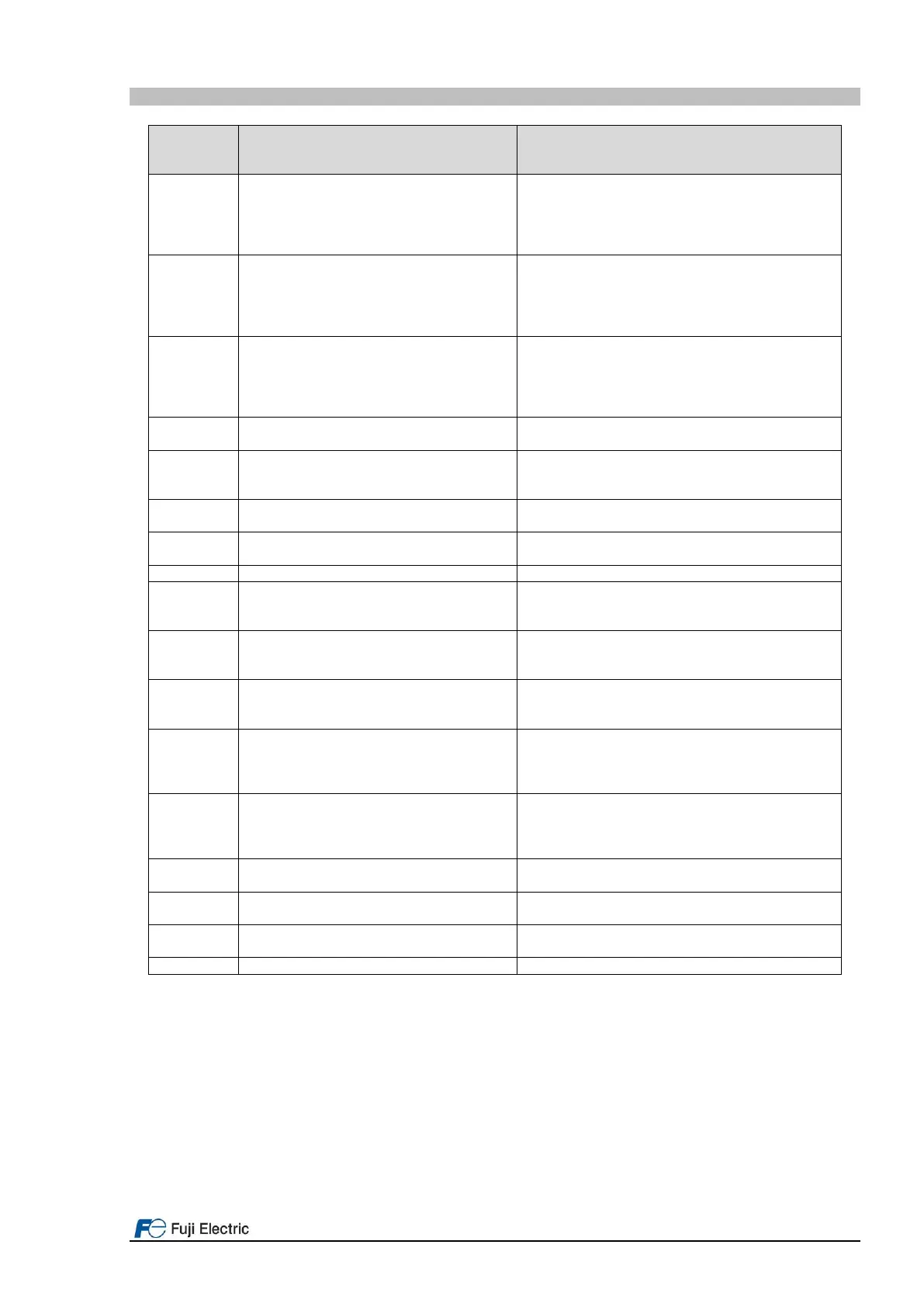
Instantaneous overcurrent
OC1= Overload during acceleration
OC2= Overload during deceleration
OC3= Overload during constant speed
Check if the motor used in the application has
been selected properly.
Check if the inverter used in the application has
been selected properly.
Check if brake opens.
Overvoltage in inverter DC link:
OV1= Overvoltage during acceleration
OV2= Overvoltage during deceleration
OV3= Overvoltage during constant speed
Braking resistor not connected or defective.
Counterweight not counterbalanced.
Deceleration time too short.
Check connection.
Check mains connection.
Undervoltage in inverter DC link
Supply voltage too low.
Mains supply failure.
Acceleration too fast.
Load too high.
Check connection of the input signal.
Check inverters input protections.
Check input connections.
Misconnection on inverters side.
Misconnection on motors side.
Misconnection on main contactors.
Inverter fan defective.
Ambient temperature too high.
Digital input programmed with value 9 (THR) is
not active.
Inverter internal overheat
Check temperature inside electrical cabinet.
Motor protection (PTC/NTC thermistor)
Motor fan too small.
Ambient temperature too high.
Check setting of H26 and H27.
Charging resistor overheat
The temperature of the charging resistor inside
the inverter has exceeded the allowed limit.
Reduce number of Power ON/OFF.
Braking resistor overheat (Electronic
protection)
The temperature of the braking resistor has
exceeded the allowable value (power too small).
Check setting on F50, F51, F52.
Check brake.
Motor, car or counterweight blocked.
Inverter at current limit, possibly too small.
Check functions F10~F12.
Over temperature in IGBT.
Failure in the cooling system.
Switching frequency (function F26) too high.
Car load too high.
Zero-phase current caused by ground fault in the
output circuit has exceeded the allowable limit.
An error has occurred when writing data to the
inverter memory.
Keypad communication error
A communication error has occurred between the
keypad and the inverter.
Failure in the inverter CPU.
* These alarms can change enable/disable by a function code.

 Loading...


