Page 18 of 28 Fuji Electric Europe GmbH
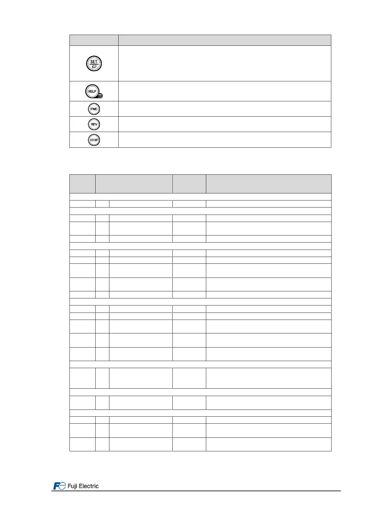
Set key which works as follows according to the operation modes.
In Running mode: Pressing this key switch to the selection screen of the LCD monitor content.
In Programming mode: Pressing this key establishes the selected items and data being changed.
In Alarm mode: Pressing this key switch to the alarm detailed information screen.
Pressing this key call up the HELP screen according to the current display state.
Holding it down for 2 seconds toggles between the remote and local modes.
Pressing this key starts running the motor in the forward rotation (when local mode).
Pressing this key starts running the motor in the reverse rotation (when local mode).
Pressing this key stops the motor (when local mode).
7.2.2 Keypad menus
Table 8.6: Keypad menus organization and its function.
0. Quick Setup: Shows only frequently used function codes.
1. Start-up: Sets functions for initial settings.
Sets language to be displayed on LCD monitor.
Allows individual initialization of function codes that are grouped
by application.
Selects content to be displayed on LCD screen.
2. Function Code: Setting screens related to function codes, such as setting/copying function code data.
Allows function code data to be displayed/changed.
Allows confirmation of function code settings.
Allows confirmation of function code changes from factory-
default settings.
Reads, writes and verifies function code data between the
inverter and the keypad.
Restores function code data values to factory-default settings.
3. INV Information: Allows monitoring of inverter operational status.
Displays operational information.
Displays external interface information.
Displays cumulative run time and other information used during
maintenance.
Allows confirmation of inverter type, serial number and ROM
version.
Allows confirmation and setting of travel direction counter. This
function provides the information for replacing wire/rope.
4. Alarm Information: Displays alarm information.
Lists alarm history (newest + 3 previous). Also this allows you to
view the detail information on the running status at the time when
alarm occurred.
5. User Configure: Allows any settings to be made.
Allows function codes to be added to or deleted from the "Quick
Setup".
6. Tools: Various functions
Customizable logic monitor
Previews status of each step in customizable logic.
Allows measurement of the operational status of the maximum
output current and average output current.
Allows monitoring and setting of function codes for
communication (S, M, W, X, Z, etc.)
7.2.3 Example of function setting

 Loading...


