Page 17 of 28 Fuji Electric Europe GmbH
7.2 TP-A1-LM2 (Advanced keypad)
7.2.1 Keypad keys
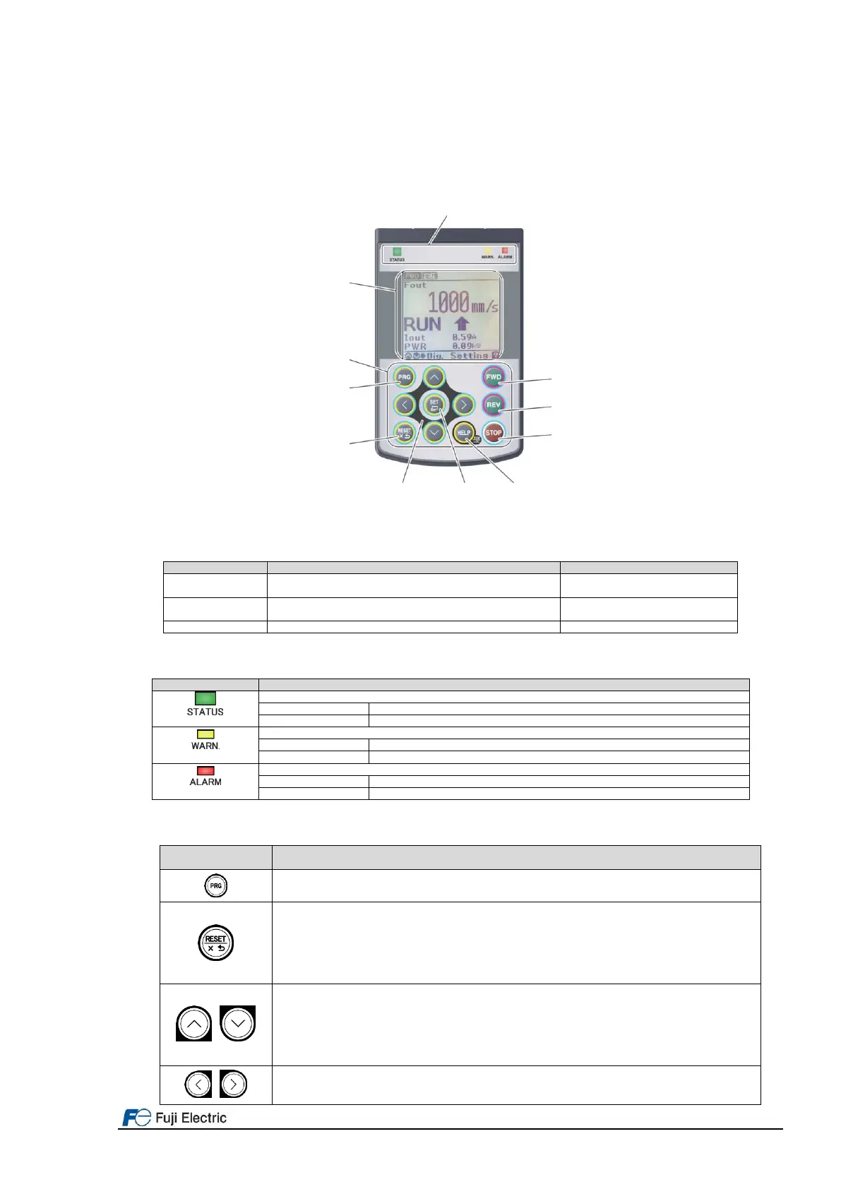
Keypad “TP-A1-LM2” allows the user to run and stop the motor locally, monitor the running status, set the function
code data, and monitor I/O signal states, maintenance information, and alarm information. Figure 8.5 shows an
overview of TP-A1-LM2. Table 8.3 explains the three main areas of the keypad.
Figure 8.5: Names and Functions of Keypad Components
Table 8.3: Keypad overview.
These indicators show the current running status of the
inverter.
This monitor shows the following various information about the
inverter according to the operation modes.
These keys are used to perform various inverter operations.
Table 8.4: Indication of LED Indicators.
Shows the inverter running state.
No run command input (Inverter stopped)
Shows the warning state (light alarm).
No light alarm has occurred.
A light alarm has occurred. But inverter can continue running.
Shows the alarm state (heavy alarm).
No heavy alarm has occurred.
A heavy alarm has occurred. Inverter shuts off its output.
Table 8.5: Overview of Keypad Functions.
This key switches the operation modes between Running mode/Alarm mode and Programming mode.
Reset key which works as follows according to the operation modes.
In Running mode: This key cancels the screen transition.
In Programming mode: This key discards the settings being configured and cancels the screen transition.
In Alarm mode: This key resets the alarm states and switches to Programming mode.
UP/DOWN key which works as follows according to the operation modes.
In Running mode: These keys switch to the digital reference speed (when local mode).
In Programming mode: These keys select menu items, change data, and scroll the screen.
In Alarm mode: These keys display multiple alarms and alarm history.
These keys move the cursor to the digit of data to be modified, shift the setting item, and switch the screen.
UP/DOWN/LEFT/RIGHT arrow key

 Loading...


