Page 14 of 28 Fuji Electric Europe GmbH
7. Keypad operation
7.1 TP-E1U (Basic keypad)
7.1.1 Led monitor, keys and LED indicators on the keypad
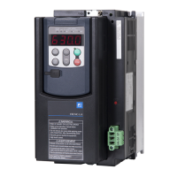
As shown on figure 8.1, the keypad consists of a four-digit LED monitor, six keys, and five LED indicators.
The keypad allows you to monitor the running status, specify the function code data, and monitor I/O signal states,
maintenance information, and alarm information. The meaning of each part of the keypad is explained on table 8.1.
Figure 8.1: Keypad overview
Table 8.1: Overview of Keypad Functions
LED Monitor,
Keys, and LED
Indicators
Four-digit, 7-segment LED monitor which displays the followings according to the operation modes.
In Running mode: Running status information (Monitoring data according to E52 setting).
In Programming mode: Menu, function codes and their data.
In Alarm mode: Alarm code, which identifies the alarm factor when the protective function is activated.
Program/Reset key which switches the operation modes of the inverter.
In Running mode: Pressing this key switches the inverter to Programming mode.
In Programming mode: Pressing this key switches the inverter to Running mode.
In Alarm mode: Pressing this key after removing the alarm factor will switch the inverter to Running
mode.
Function/Data key which switches the operations you want to do in each mode as follows:
In Running mode: Pressing this key switches the information to be displayed (Monitor data fixed on
E52).
In Programming mode: Pressing this key displays the function code or establishes the data entered with
and keys.
In Alarm mode: Pressing this key displays the details of the problem indicated by the alarm code that
has come up on the LED monitor.
Together with , keypad moves to Programming mode in case of Alarm status.
UP and DOWN keys. Press these keys to select the setting items and change the function code data displayed on
the LED monitor.
Lights when running with a run command entered by terminal command FWD or REV or through the
communications link.
Lights when the inverter is ready to run with a run command.
These three LED indicators identify the unit of numeral displayed on the LED monitor in Running mode by
combination of lit and unlit states of them.
Unit: Hz, A, kW, r/min and m/min.
While the inverter is in Programming mode, the LEDs of Hz and kW light. Hz A kW
Lights when the data to display exceeds 9999. When this LED lights, the "displayed value x 10" is the actual
value.
Example: If the LED monitor displays
1234
and the x10 LED lights, it means that the actual value is "1,234
10 = 12,340."
The USB port with a Mini-B connector enables the inverter to connect with a PC with an USB cable.

 Loading...


