GIA 63/GIA 63W Installation Manual Page 4-13
190-00303-05 Revision S
4.2 Power and Antennas
4.2.1 Power Functions
This section covers the power input requirements.
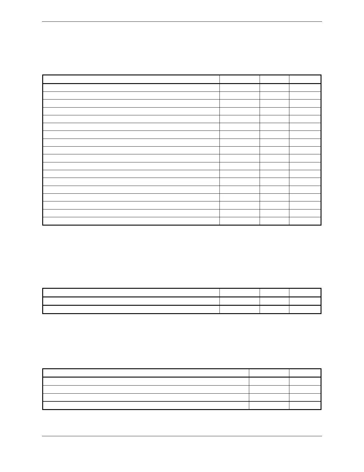
4.2.1.1 Aircraft Power
Pin Name Connector Pin I/O
AIRCRAFT POWER 1 P601 17 In
AIRCRAFT POWER 1 P601 19 In
AIRCRAFT POWER 1 P601 21 In
AIRCRAFT POWER 2 P601 23 In
AIRCRAFT POWER 2 P601 25 In
AIRCRAFT POWER 2 P601 27 In
AIRCRAFT POWER 1 P605 29 In
AIRCRAFT POWER 1 P605 31 In
AIRCRAFT POWER 2 P605 33 In
AIRCRAFT POWER 2 P605 35 In
POWER GROUND P601 30 --
POWER GROUND P601 31 --
POWER GROUND P601 43 --
POWER GROUND P601 44 --
POWER GROUND P602 61 --
POWER GROUND P602 62 --
POWER GROUND P605 76 --
POWER GROUND P605 78 --
Pins 17, 19, and 21 of P601 are internally connected to form AIRCRAFT POWER 1. Pins 23, 25, and 27
of P601 are internally connected to form AIRCRAFT POWER 2. AIRCRAFT POWER 1 and
AIRCRAFT POWER 2 are “diode ORed” to provide power redundancy. The same applies to pins 29/31
and pins 33/35 of P605.
4.2.1.2 Remote On/Off
Pin Name Connector Pin I/O
GIA REMOTE POWER OFF P605 36 In
COM REMOTE POWER OFF P601 16 In
INACTIVE: Vin ≤ 3.5VDC
ACTIVE: 10 ≤ Vin ≤ 33VDC with ≥ 75 uA source current
Source current is internally limited to 1.5 mA max for a 10-33VDC input
4.2.1.3 Antennas
Pin Name Connector I/O
GPS ANTENNA P611 In
COM ANTENNA P612 I/O
VOR/LOC ANTENNA P613 In
GLIDESLOPE ANTENNA P614 In

 Loading...


