Page 4-20 GIA 63/GIA 63W Installation Manual
Revision S 190-00303-05
4.7 VOR/ILS Indicator
4.7.1 VOR/ILS Indicator Function
The VOR/ILS indicator displays both lateral and vertical, To/From indications, lateral flags, vertical
flags, and superflags.
VOR/LOC COMPOSITE OUT is a standard VOR/localizer composite signal which may be used to drive
the Left/Right, TO/FROM, and Flag indications of certain navigational indicators that contain an internal
converter.
GLIDESLOPE COMPOSITE OUT (011-01105-20 ONLY) is a standard glideslope composite signal
which may be used to drive UP/DOWN and Flag indications of certain navigational indicators that
contain an internal converter.
The ILS ENERGIZE* output goes low when the VLOC frequency is channeled to a localizer channel.
4.7.2 VOR/ILS Indicator Electrical Characteristics
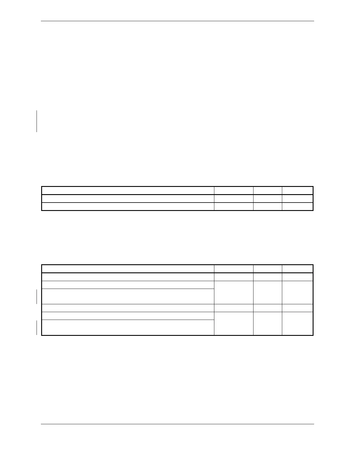
4.7.2.1 Superflags
Pin Name Connector Pin I/O
VOR/LOC SUPERFLAG P602 15 Out
GLIDESLOPE SUPERFLAG P602 38 Out
The output supplies not less than 500 mA on a 28 volt system with the output voltage not less than
(AIRCRAFT POWER – 1.5 V
DC
) when the flag is to be OUT OF VIEW. The output voltage with respect
to ground is less than 0.25 V
DC
when the flag is to be IN VIEW.
4.7.2.2 Deviation
Pin Name Connector Pin I/O
VOR/LOC +LEFT P602 5 Out
VOR/LOC +RIGHT (VOR/LOC COMMON)
VOR/LOC +RIGHT (NAV COMMON) (011-01105-20
ONLY)
P602 6 Out
GLIDESLOPE +UP P602 34 Out
GLIDESLOPE +DOWN (GLIDESLOPE COMMON)
GLIDESLOPE +DOWN (NAV COMMON) (011-01105-20
ONLY)
P602 55 Out
The deviation outputs are each capable of driving up to three 1000 Ω meter loads with ±150 mV
DC
±10%
with respect to 2.5V Common for full-scale deflection. The drive circuit provides for more than full-scale
deflection with a maximum course deviation output voltage of ±300 mV
DC
±10%.

 Loading...


