GIA 63/GIA 63W Installation Manual Page 4-17
190-00303-05 Revision S
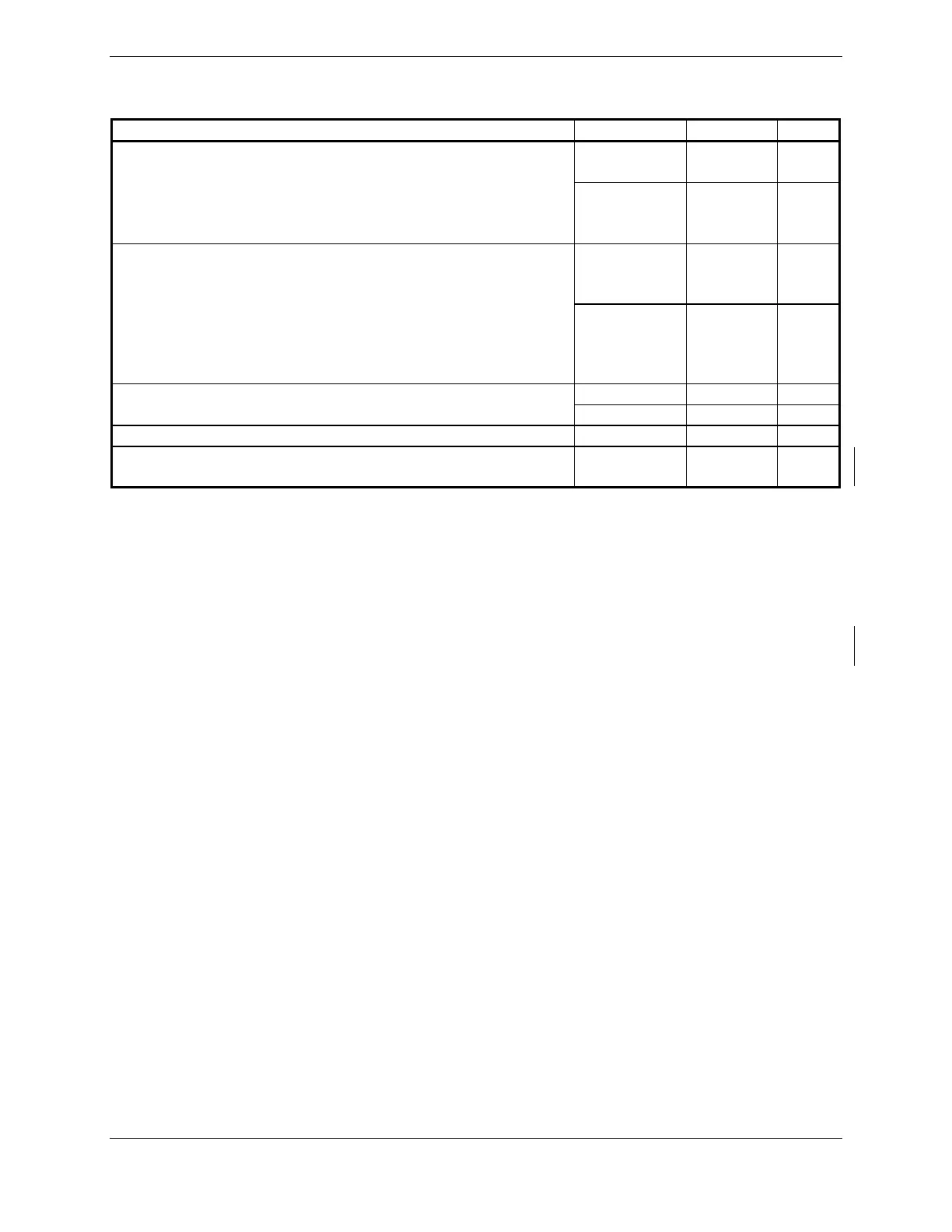
4.5 Discrete I/O
Pin Name Connector Pin I/O
P604 4, 5, 10,
15, 16
In DISCRETE IN
P605 3, 12, 16,
50-51,
60, 74
In
P604 7-9, 12-
14, 17-
21, 24
In DISCRETE IN*
P605 37-46,
49, 52-
55, 59,
73
In
P605 47, 68-70 Out DISCRETE OUT*
P606 67-75, 77 Out
ANNUNCIATE* P605 71, 72 Out
ANNUNCIATE* P604 1, 6, 25-
44
Out
DISCRETE IN* pins:
INACTIVE: 10 ≤ Vin ≤ 33VDC or Rin ≥ 100kΩ
ACTIVE: Vin ≤ 1.9VDC with ≥ 75 uA sink current, or Rin ≤ 375Ω
Sink current is internally limited to 200 uA max for a grounded input
DISCRETE IN pins:
INACTIVE: Vin ≤ 3.5VDC or open
ACTIVE: 6.5 ≤ Vin ≤ 33VDC with ≥ 75 uA source current
Source current is internally limited to 1.5 mA max for a 10-33VDC input
DISCRETE OUT* pins:
INACTIVE: Floating (can be pulled up to externally sourced Vout in the range 0 ≤ Vout ≤ 33VDC)
Leakage current in the INACTIVE state is typically ≤ 10 uA to ground
ACTIVE: Vout ≤ 0.5VDC with ≤ 20 mA sink current
Sink current must be externally limited to 20 mA max
ANNUNCIATE* pins:
INACTIVE: Floating (can be pulled up to externally sourced Vout in the range 0 ≤ Vout ≤ 33VDC)
Leakage current in the INACTIVE state is typically ≤ 250 uA to ground
ACTIVE: Vout ≤ 0.5VDC with ≤ 500 mA sink current
Sink current must be externally limited to 500 mA max

 Loading...


