GTS 8XX/GPA 65 Installation Manual Page 4-7
190-00587-00 Revision 4TP
4.3 Power
4.3.1 Aircraft Power Functions
This section covers the power input requirements.
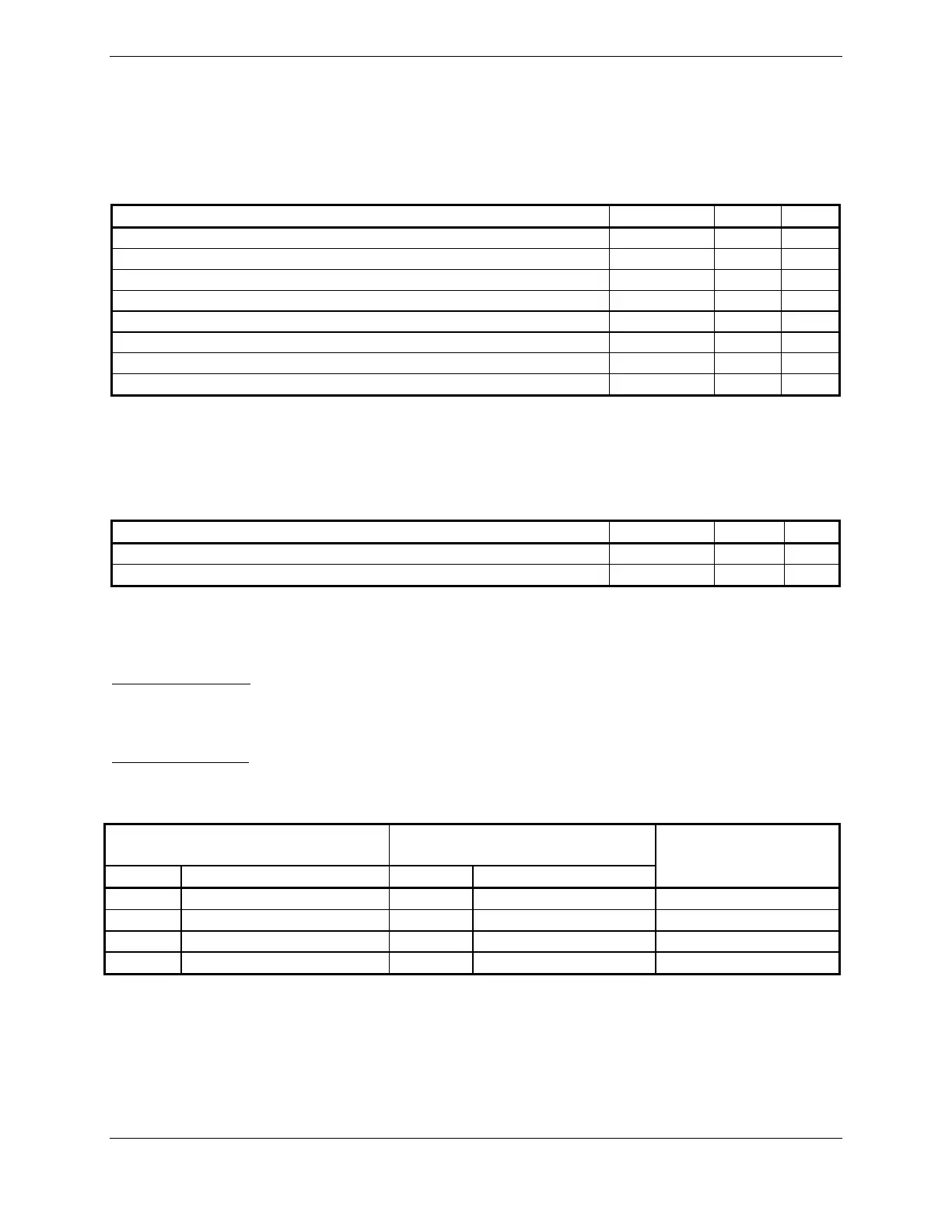
4.3.1.1 Aircraft Power
Pin Name Connector Pin I/O
AIRCRAFT POWER 1 P8003 2 In
AIRCRAFT POWER 1 P8003 3 In
AIRCRAFT POWER 2 P8003 4 In
AIRCRAFT POWER 2 P8003 5 In
AIRCRAFT GROUND P8003 21 --
AIRCRAFT GROUND P8003 22 --
AIRCRAFT GROUND P8003 23 --
AIRCRAFT GROUND P8003 24 --
Pins 2 and 3 are internally connected to form AIRCRAFT POWER 1. Pins 4 and 5 are internally
connected to form AIRCRAFT POWER 2. AIRCRAFT POWER 1 and AIRCRAFT POWER 2 are
“diode ORed” to provide aircraft power redundancy.
4.3.1.2 Remote Power
Pin Name Connector Pin I/O
TRAFFIC SYSTEM REMOTE POWER ON* P8003 18 In
TRAFFIC SYSTEM REMOTE POWER OFF P8003 36 In
An asterisk (*) following a signal name denotes that the signal is Active Low.
Used to remotely control power.
Remote Power ON*
ACTIVE: Vin < 3 VDC or grounded (Unit ON)
INACTIVE: Vin > 8 VDC or floating (Unit OFF)
Remote Power OFF
ACTIVE: Vin > 8 VDC (Unit OFF)
INACTIVE: Vin < 3 VDC or floating (Unit ON)
Active Low Remote Power On
(J8003 Pin 18)
Active High Remote Power Off
(J8003 Pin 36)
State Level State Level
Expected Unit State
Inactive Vin > 8 VDC or Open Inactive Vin < 3VDC or Open OFF
Active Vin < 3VDC or Gnd Inactive Vin < 3VDC or Open ON
Inactive Vin > 8 VDC or Open Active Vin > 8 VDC OFF
Active Vin < 3VDC or Gnd Active Vin > 8 VDC OFF
 Loading...