Page 4-12 GTS 8XX/GPA 65 Installation Manual
Revision 4TP 190-00587-00
4.5 Configuration
4.5.1 Configuration Module
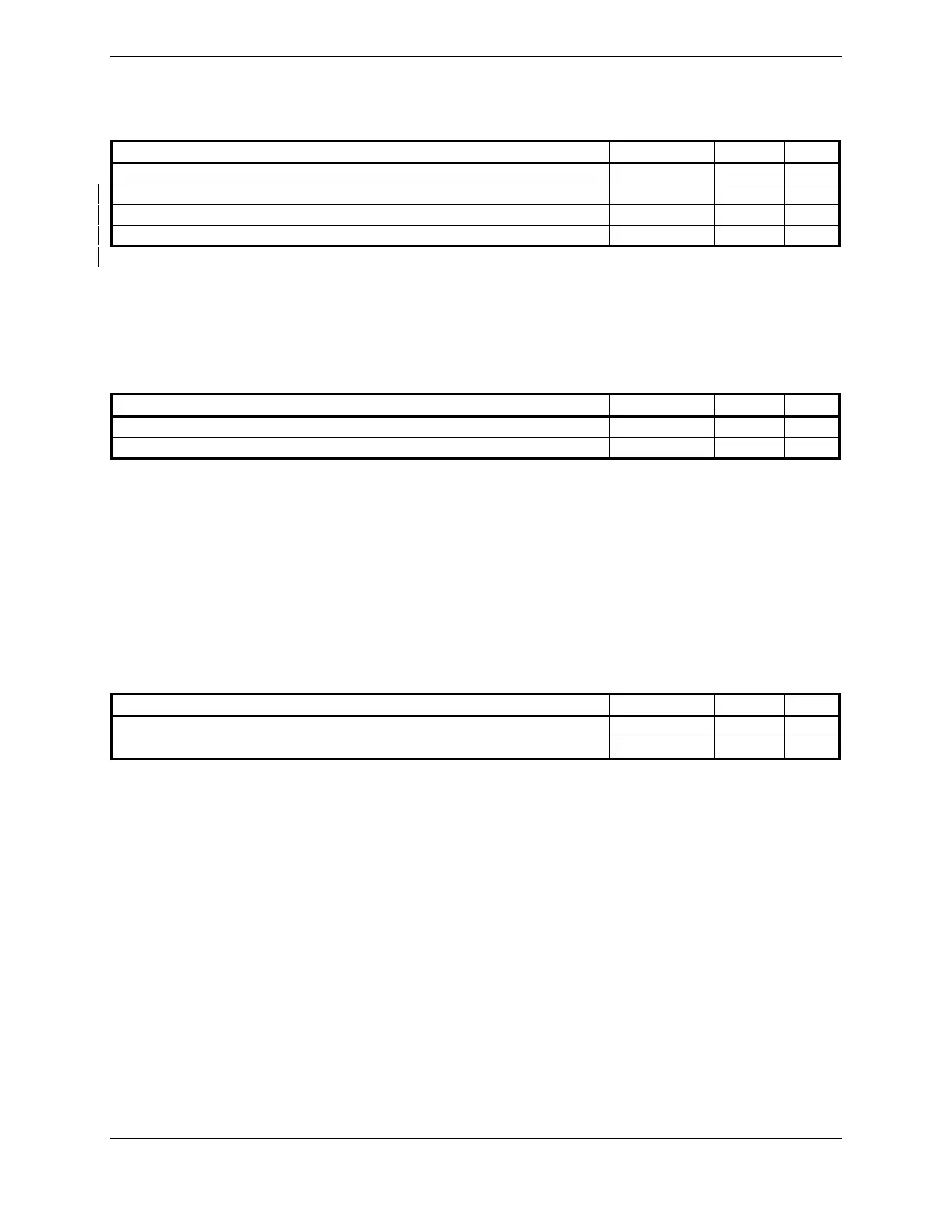
Pin Name Connector Pin I/O
CONFIG MODULE GND P8001 1 --
CONFIG MODULE PWR OUT** P8001 21 --
CONFIG MODULE DATA** P8001 40 I/O
CONFIG MODULE CLK** P8001 60 I/O
**Signals have ESD (Electrostatic Discharge) protection, but not lightning protection.
4.6 Analog/Discrete
4.6.1 Heading Input
4.6.1.1 26 Volt AC References
Pin Name Connector Pin I/O
26 VAC HEADING REF HI P8002 63 In
26 VAC HEADING REF LO P8002 64 In
Used to sample AC inputs.
This signal must be the same phase and frequency as the indicator being driven.
Frequency: 400 Hz ± 10%
Voltage: 22.6 Vrms to 28.6 Vrms
Input Impedance:
>10 kΩ
4.6.1.2 Radar Altimeter
Pin Name Connector Pin I/O
ANALOG RADAR ALTIMETER HI P8002 71 In
ANALOG RADAR ALTIMETER LO P8002 72 In
Provides altitude information during approach.
 Loading...