Page 4-14 GTS 8XX/GPA 65 Installation Manual
Revision 4TP 190-00587-00
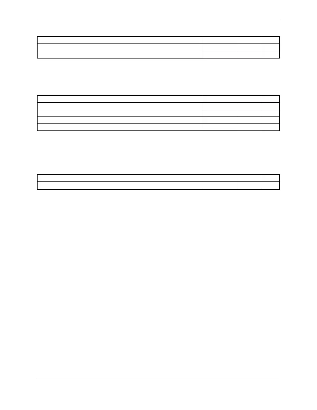
4.6.5 Active High Discrete Inputs
Pin Name Connector Pin I/O
HEADING VALID P8002 68 In
ANALOG RADAR ALTIMETER VALID P8002 76 In
ACTIVE: 8 V ≤ Vin ≤ 36 V
INACTIVE: 0 V ≤ Vin ≤ 3.5 V, or Rin ≥ 100k ohms
Sink current is internally limited to approximately 1 mA typical for an input connected to +28VDC.
4.6.6 Annunciator Output
Pin Name Connector Pin I/O
TA DISPLAY ENABLE* P8002 50 Out
AURAL TA ALERT* P8002 51 Out
VISUAL TA ALERT* P8002 53 Out
TRAFFIC SYSTEM STATUS VALID* P8002 54 Out
An asterisk (*) following a signal name denotes that the signal is Active Low.
ACTIVE: 0 V ≤ Vout ≤ 0.5 V or Rout ≤ 10 ohms, sinking up to 500 mA
INACTIVE: Rout ≥ 100k ohms to ground, withstanding up to +36 VDC.
4.7 Mutual Suppression Bus
Pin Name Connector Pin I/O
EXTERNAL SUPPRESSION I/O P8002 48 I/O
Mutual Suppression Input/Output bus compliant with ARINC 735A Attachment 8, with the exception that
the maximum applied DC steady state voltage is +30.3V. Suppression I/O signal is pulsed under normal
operation.
 Loading...