S47183-e 01/2008 Design and specifications are subject to change without notice 11
• The sensor includes Hall-probes and delivers a propor-
tional signal-output to the SEL control. The signal-
processing unit transforms input signal, into standard
output signals shown in the table below.
• The outputs are insulated from the main voltage. The in-
sulation withstands voltages up to 4kV RMS and up to
40kV in peak.
• Two versions are available. Standard model (T35) for
ambient temperature -5°C…+35°C and the model for
higher temperature (T55) -5°C…+55°C.
• More details can be found in separate instruction for SEL
usage.
Type SEL 06-1 06-2 06-4 12-1 12-2 12-4
Input - 6kA…+6 kA -12kA…+12kA
U
Ne
[V] 1000 2000 4000 1000 2000 4000
T35 for ambient temperature of the breaker
-5°C…+35°C / +23°F…+95°F
T55 for ambient temperature of the breaker
-5°C…+55°C / +23°F...+131°F
I
Ne
Relating to the rated current of the breaker
Output 4...20mA
-20...20mA
-10...10V
U
Ni
[kV] 12 18 40 12 18 40
3.2.13 Electronic control system
All the control units are installed in control box [Fig. 18].
Starting from the left, these are:
Fig. 18 Control box with control units
• (1) NEKO control unit [Fig. 19-1] – internal control unit
with capacitors’ bank. It releases firing signal for ED coil
(-X2 :10/:11) and enable signalization of the capacitors’
charging (-X3 :6/:7). NEKO control unit also blocks the fir-
ing signal until C-bank is fully charged (~15sec).
• NEKO unite requires high quality firing signal. Be sure,
that voltage level is between 6V…24V and there is no
short spikes on signal (<3msec). This can lead to major
defect of the NEKO control unit!
Fig. 19-1 NEKO control unit
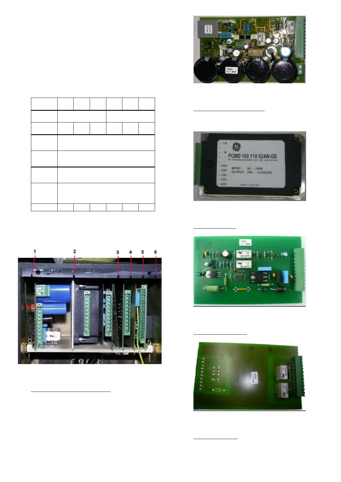
• (2) internal voltage converter (code nr: 8) - converts ex-
ternal supply voltage (-
X3 :4/:5) to the internal 24VDC,
required by controls (except for the drive supply).
Fig. 19-2 Voltage converter 110V/24V DC
• (3) SU control unit – see point 3.2.11.
Fig. 19-3 SU control unit
• (4) ST/UVR control unit –
simple relays’ system. It controls
operation of shunt trip or zero voltage release.
Fig. 19-4 ST/UVR control unit
• (5) SEL control unit – see point 3.2.12 [Fig. 17].
 Loading...


