14 Design and specifications are subject to change without notice 01/2008
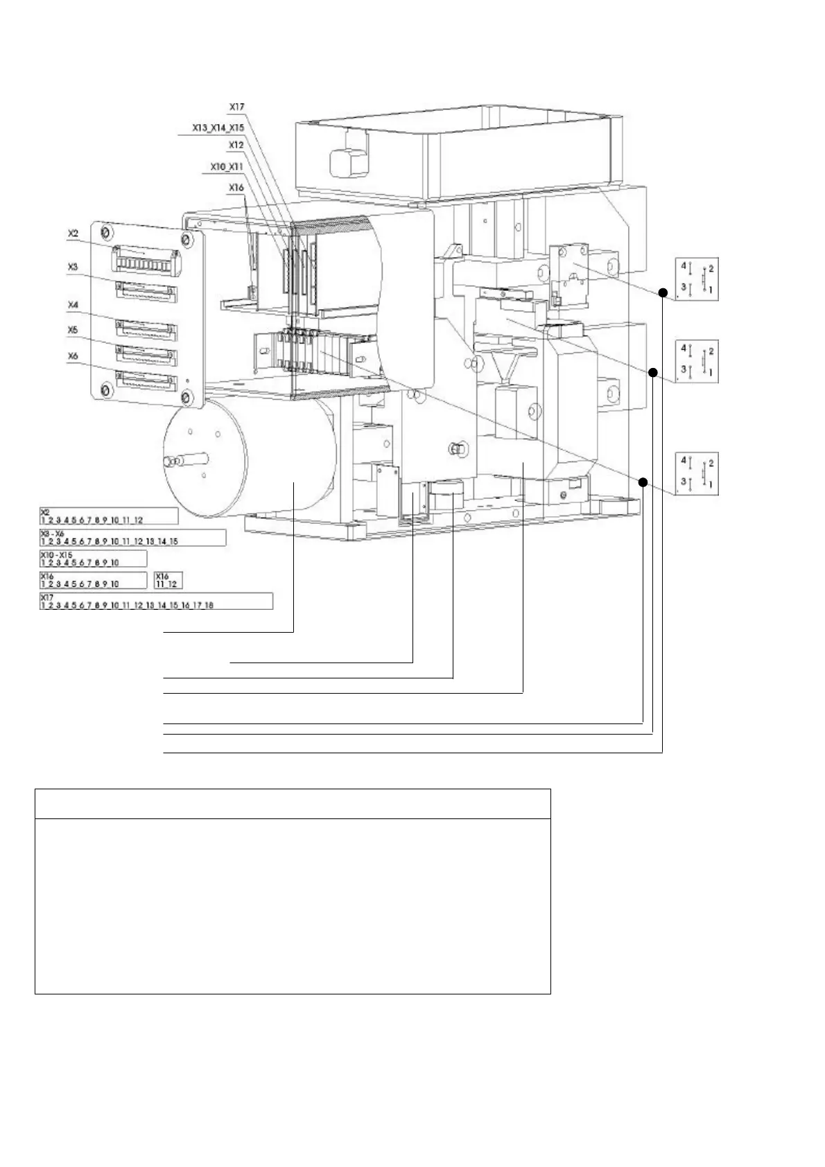
4.1 Controls layout
Closing solenoid drive
Shunt trip / Zero voltage release
ED coil
OCT device
HS 1...HS 10
OCT indicator
Arc chute-indicator
Description
Designation
X2 1.Connector: Auxiliary- and control circuits
X3 2.Connector: Auxiliary- and control circuits
X4 3.Connector: Auxiliary contacts HS1...HS5
X5 4.Connector: Auxiliary contacts HS6...HS10
X6 5.Connector: Current measure system SEL
X10 Control board: Voltage converter
X11 Control board: Interface for external DC 24V supply (OPTION)
X12 Control board: SU control unit
X13 Control board: Shunt trip control unit
X14, X15 Control board: Zero voltage release (X15: with modified UVR)
X16 Control board: NEKO control unit for ED coil control
X17 Control board: Current measure system SEL
Fig. 20 Control system’s layout
 Loading...


