S47183-e 01/2008 Design and specifications are subject to change without notice 7
3.2.3 Mechanism
• The Gerapid is equipped with a modular designed
mechanism, wear-resistant and nearly maintenance-
free. This mechanism ensures an extended electrical
and mechanical endurance of the breaker as well as a
high amount of safety for all operation conditions.
• This mechanism is mechanically latched in CLOSE posi-
tion. The principle of a mechanical latch mechanism of-
fers the big advantage, contrary to often used holding
magnet system. No auxiliary control power source is re-
quired to keep close.
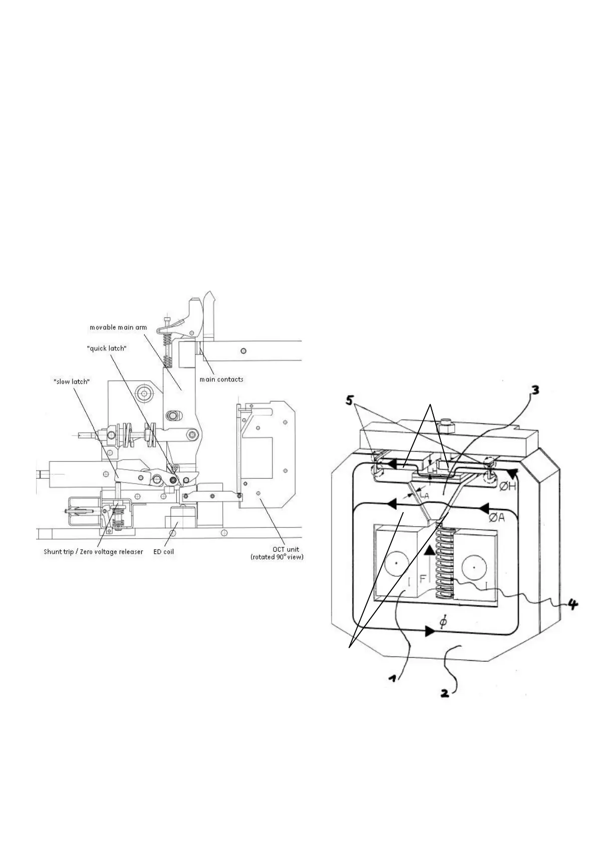
• The mechanism is provided with two latches [Fig. 6]. One
of the latches, “slow latch”, is used for opening under
normal conditions, like actuation of shunt trip or zero-
voltage release. The other one, “quick latch”, de-clutches
the main contact arm from the mechanism and open
contacts with an extremely short delay. This is used in
case of short-circuit or overloads. All safety releases op-
erate onto this latch.
Fig. 6 Latching and tripping system
3.2.4 Over-Current Tripping device (code nr: 7)
•
The OCT device is a release magnet with twin magnet
circuits, optimizing the twin magnetic field principle [Fig.
7]. This technology ensures an equally fast tripping in
both current directions.
• The magnetic system does not require an auxiliary con-
trol voltage to operate. It uses magnetic energy from the
main circuit.
• The system consists of the holding circuit [6], the mov-
able armature [3] and the tripping circuit [7]. The holding
and the tripping magnetic circuits are both excited by
main current [1]. Until the static overload release’s re-
sponse threshold has been reached, the armature [3] is
held in position by the holding flux (Φ
counter spring’s force [4]. Once the main current ex-
ceeds the set static response threshold, the attraction
flux (ΦA) [2] takes over and pulls rapidly down the flexi-
ble armature [3]. During this operation, the armature hit
the
seesaw, which releases the quick latch in the
mechanism. The latch and contacts are opened imme-
diately.
• The response threshold can be easily adjusted by turn-
ing the adjustment nut with a SW6 hexagon wrench as
described in point 2.3.2.
• In combination wit
h the transparent side protection
covers (code nr: 15), a fixed mounted insulated knob is
available to enable OCT adjusting [Fig. 16].
1. Current flow direction.
2. Magnetic core with two fluxes (holding flux ΦH and attracting flux ΦA).
3. Movable anchor.
4. Pressure spring for movable anchor.
5. Short circuit rings.
6. Holding magnetic circuit.
7. Tripping magnetic circuit.
Fig. 7 OCT device
6
7
 Loading...


