S47183-e 01/2008 Design and specifications are subject to change without notice 19
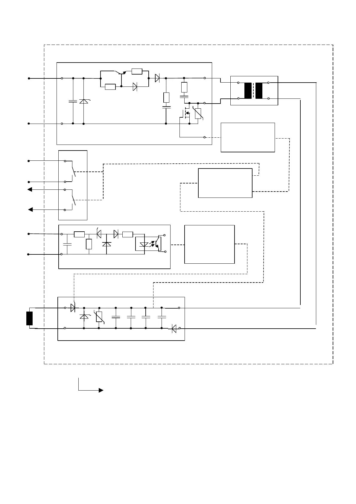
4.3.4 NEKO control unit
• Releasing signal at (-X2 :10/:11) is processed by optocoupler, pay attentions to the polarity !
• Emergency STOP signal is provided to lock CLOSE command, until capacitors will be charged.
• Be sure, that voltage level is between 6V…24V and there is no interfere spikes (<3ms) on firing signal. This can lead to
major defect of the NEKO control unit!
• Maximum duration of the firing command must not exceed ~1sec. Longer signal will lead to NEKO failure! It is highly
recommended to use an internal auxiliary contact in serial connection with firing circuit (-X2 :10/:11). It will automatically
cut off the firing circuit after contacts are opened.
Fig. 25 ED coil with internal NEKO control unit
bank charged
-X10, 11
X10, 11
Charging control
Insulating Transformer
Firing signal control
and transforming
Meldeschalter
-24V
+
-
+
-X16
3
4
5
6
9
10
1
2
11
12
-X3
-X3
-X2
-X2
:8
:6
:6
:7
:10
:11
Capacity and firing thyristor
Key position - 3
Key number – 2: With ED coil and internal NEKO control unit.
 Loading...


