46 Design and specifications are subject to change without notice 01/2008
6.2.5 Adjusting the auxiliary switches
1. OPEN the breaker.
2. Disconnect power supply, and pull out all the
plugs from control box’s terminals.
3. In case of NEKO control unit inside, wait 1 minute
until capacity will discharge.
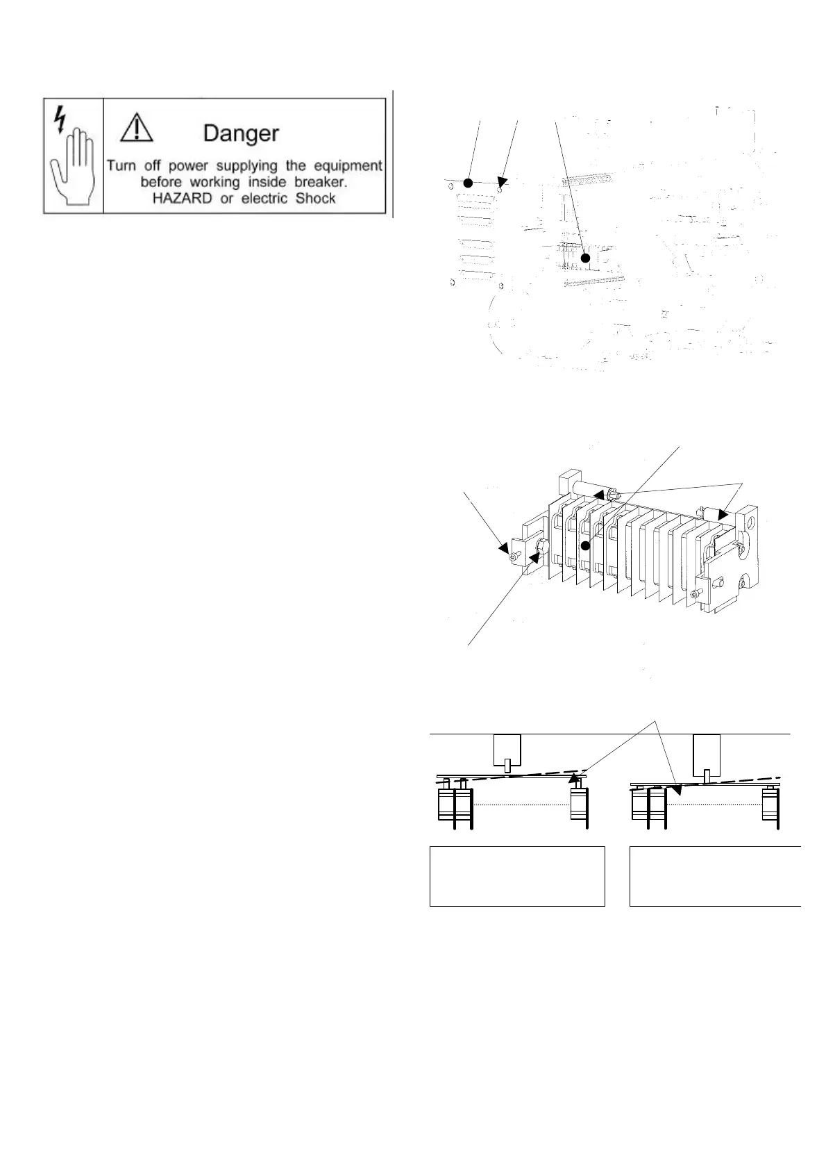
• Adjustment of the switches is required in case of in-
correct position signalization. This might happen due
to not simultaneous activation of the switches, by ac-
tuating plate (6) [Fig. 56-3], dashed line.
• In case of only 3 or 5 switches, installed in centre of
the block, it shall not occur (breaker after 2003).
• In case of 10 switches or when switches are mounted
at the far left position, it might be needed (breaker be-
fore 2003). In most cases, only far left or far right
mounted switches might need to be re-adjusted.
• Check all the switches signalization to establish, which
of these need to be re-adjusted (left or right side).
• OPEN the breaker.
• [Fig. 56-1] Loosen four screws (2). Move the front cover
(1) slowly down. The auxiliary switch block (3) is acces-
sible now, in the bottom compartment.
• [Fig. 56-2] Loosen screws (4) on the side, which needs
to be re-adjusted. Turn the proper (left or right) adjust-
ing screw (5) clockwise, until all missing signals switch
over.
Warning! Too much turning in, may effect with full
pressing of the switches’ pin and its breakdown.
• [Fig. 56-1] Check the correct signalization of all
switches at the connecting plug terminations X4, X5! If
necessary re-adjust the switches from other side.
• Now tighten solid the screws 4.
• [Fig. 56-1] Close the control box with front cover (1) by
fixing the four screws (2). Pay attention, that no cables
will be crushed between box and front plate.
• CLOSE the breaker several times. Check if the auxiliary
contacts are switching over correctly.
• Finally check the electrically functions in the “TEST-
position” of the draw-out version after installing the
breaker into the substation.
If re-adjustment does not help, please contact GE Service
Team. It might be required to install switch block again or
to move switches to centre of the block for better per-
formance.
Fig. 56-1 Control box with auxiliary switch block
Fig. 56-2 Auxiliary switch block
Fig. 56-3 Actuating plate for auxiliary switch block
Gerapid in position „ON“:
Main contacts closed.
Aux. switches not actuated
Gerapid in position „OFF“:
Main contacts open.
Auxiliary switches actuated
2 1
5
3
6
 Loading...


